The EaseRobot Series 8: Building an Autonomous House Bot with ROS
Introduction
The EaseRobot project is a hobbyist robotic project aimed at designing and constructing an autonomous house-bot using ROS (Robot Operating System). This article marks the eighth installment in the series documenting the project's progress.
Background
In the initial phase, we defined the requirements for our robot by selecting a primary mission and breaking it down into specific Design Goals for clarity and manageability.
The mission, inspired by the article "Let's build a robot!", focuses on creating a robot capable of recognizing family members and functioning as a messenger and reminder. For instance, one could say, "Robot, remind (PersonName) to pick me up from the station at 6 pm." Even if the intended recipient's phone is on silent or they are occupied, the robot autonomously navigates through the house, locates the individual, and delivers the message.
The Design Goals established for this mission include:
- Design Goal 1: Implement camera-based face detection and identification to display messages for recognized individuals.
- Design Goal 2: Integrate capabilities for facial expressions and speech synthesis to effectively deliver messages.
- Design Goal 3: Enable locomotion control via remote keyboard and/or joystick.
- Design Goal 4: Incorporate a laser range finder or similar sensor to aid in navigation.
- Design Goal 5: Achieve autonomous locomotion, previously implemented using the ROS Navigation Stack.
- Design Goal 6: Implement task assignment and completion notification functionalities.
In the previous installment, we integrated the ROS Navigation Stack to achieve autonomous locomotion for EaseRobot, setting navigation goals using the visualization tool rviz. In this article, we will further enhance EaseRobot by adding mission-specific code to navigate different areas of the house and locate specific individuals to deliver messages. Locations to visit will be defined in a yaml file.
To support these enhancements, we will update the ease_robot and ease_robot_missions
packages, and introduce a new package to interface LEDs and pushbuttons with the Raspberry Pi
GPIO.
Revisiting State Machines with Smach
In our previous tutorial, we delved into the world of state machines using the Smach ROS package. We designed a hierarchical state machine that incorporated a lower-level state machine for the greeting mission (Mission 2). The beauty of this design lies in its modularity, making it easy to integrate new missions by simply adding lower-level state machines. In this installment, we'll take it a step further by introducing two new missions as lower-level state machines. Mission 1 will focus on delivering messages, while Mission 4 will enable the EaseRobot to return to its home location.
Before we dive into the implementation of these new missions, let's first explore how to integrate a bi-colored LED, two pushbuttons, and update the EaseRobot package to transmit the new mission data to the state machine.
Expanding EaseRobot's Capabilities with GPIO
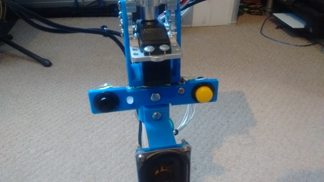
In addition to the touch screen, we're going to integrate two pushbuttons to enable users to input commands to the EaseRobot. This is necessary because the screen, being part of the robot's head, may not always be in an accessible position for user interaction. Each pushbutton will have dual functions, depending on whether the robot is currently executing a mission or not.
The first pushbutton, identified by its black color, will perform the following functions. When no mission is running and the button is pressed, the robot's head will adjust to a position suitable for user input/output on the screen. If a mission is in progress and the button is pressed, a command will be sent to cancel the current mission.
The second pushbutton, identified by its yellow color, will carry out the following functions. When no mission is running and the button is pressed, a command will be issued to execute the "Go Home" mission, which navigates the robot to a predetermined home location. During certain mission states, user acknowledgement is required, such as when the robot delivers a verbal message. In this case, pressing the yellow pushbutton will send an acknowledgement message to the state machine.
To complement the pushbuttons, we'll also add a bi-colored LED to the robot's hardware. When the EaseRobot is not executing a live mission, the LED will glow green, and when a mission is in progress, it will glow red.
Instead of incorporating the GPIO code into the EaseRobot package, we'll create a new package to handle GPIO operations, promoting code reuse. We'll write this new node using Python, leveraging an existing library for accessing the Raspberry Pi GPIO. Our ROS package, called pi_io, is located in the pi_io folder. Within this package, we'll create a ROS service to control the state of the GPIO output lines and define a custom message that will be published when one of the pushbuttons changes state.
The EaseRobot package contains all the standard ROS files and folders, including the msg folder, which holds the gpio_input.msg file that defines a custom ROS message. This message consists of two parameters: an index that refers to a specific GPIO pin, and a value that represents the current state of that pin.
The srv folder contains the gpio_output.srv file, which defines a custom ROS service. This service takes two parameters: an index that indicates which GPIO pin to set, and a value to set that pin to. The service returns a boolean success value, which is always true in the case of the Raspberry Pi, as it cannot provide feedback on the state of its GPIO pins.
The src folder contains the Python code for the node in the pi_io_node.py file. The main function initializes the ROS node and creates an instance of the PiGpioNode class. This class constructor maps the actual GPIO pins to the index values used in the message and service, and sets up the GPIO pins as inputs or outputs. It also attaches event callbacks to the input pins, which will trigger when the pins go high.
The class constructor then registers the service and message topic with ROS, and creates two timers to debounce the pushbuttons. The callback functions for the service and input events are also defined. The service callback sets the GPIO output to the specified value and returns true, while the input callbacks publish a message on the gpio/input_cmd topic when a pushbutton is pressed, after checking for button bounce.
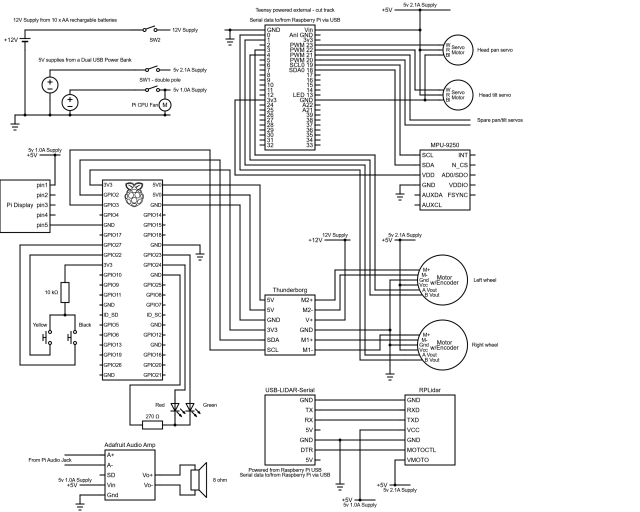
Finally, an updated circuit diagram is provided, showing how the bi-colored LED and pushbuttons are connected to the Raspberry Pi GPIO pins.
EaseRobot System Updates
To enhance the functionality of our EaseRobot system, we need to make some significant updates to the EaseRobot node. Specifically, we will modify the node to control the LED state and monitor the pushbutton topic. Additionally, we will enable the node to provide mission data for the two new missions.
Updating the Launch File
The first step is to update the ease_robot.launch file in the launch folder. This file is responsible for configuring and launching all the ROS nodes that make up our system. We need to add the new pi_io node to the launch file so that the new code runs when we launch the robot code.
To achieve this, we will add the following line to the launch file:
<node pkg="pi_io" type="pi_io_node.py" name="pi_io_node"/>
Configuring Waypoints
To enable the robot to navigate to various locations in the house, we will provide it with a list of waypoints stored in a YAML file. We will modify the EaseRobot node to accept the filename as an argument at launch. The waypoint file will have the same name as the map file with _patrol appended to the name. For example, if the map file is called second_floor, the corresponding waypoint file will be named second_floor_patrol.yaml.
We will update the launch file to pass the filename as an argument to the EaseRobot node using the following code:
<node pkg="ease_robot" type="ease_robot_node" name="ease_robot" args="-m $(find ease_robot)/maps/$(arg map_file)_patrol.yaml" output="screen"> <rosparam command="load" file="$(find ease_robot)/config/config.yaml"/> </node>
Waypoint File Structure
The waypoint file contains a list of waypoints, each with an x and y location and a direction (orientation) represented as a quaternion. The waypoints should start with w1 and be consecutive. The robot will visit each waypoint in ascending and then descending order when searching for the person to deliver the message to. The file should also include a home waypoint that the robot will navigate to when instructed to "Go Home".
Here is an example of a waypoints file:
# Waypoints must start at w1 and be consecutive
# Also have an home location
w1:
  position:
    x: -0.328835725784
    y: -0.529747009277
  orientation:
    x: 0.0
    y: 0.0
    z: 0.273852223218
    w: 0.961771781577
w2:
  position:
    x: 1.31689155102
    y: -0.944578707218
  orientation:
    x: 0.0
    y: 0.0
    z: 0.732759099845
    w: 0.680488134793
w3:
  position:
    x: 3.66307258606
    y: -0.040109038353
  orientation:
    x: 0.0
    y: 0.0
    z: 0.413215093458
    w: 0.910633453448
w4:
  position:
    x: 6.55329608917
    y: 1.04117441177
  orientation:
    x: 0.0
    y: 0.0
    z: 0.914737463209
    w: -0.404048726519
home:
  position:
    x: 0.0451934337616
    y: 0.0451934337616
  orientation:
    x: 0.0
    y: 0.0
    z: 0.224733375634
    w: 0.974420294265
Enhancements to the EaseRobot Missions Package
To facilitate the addition of new missions, we've made some adjustments to the EaseRobot missions node. Specifically, we've modified the EaseRobot_missions_node.py file and introduced two new files: take_message_to.py and go_home.py, which house the lower-level state machines.
Let's delve into the details of these two new state machines.
Mission 1 - "Deliver a Message"
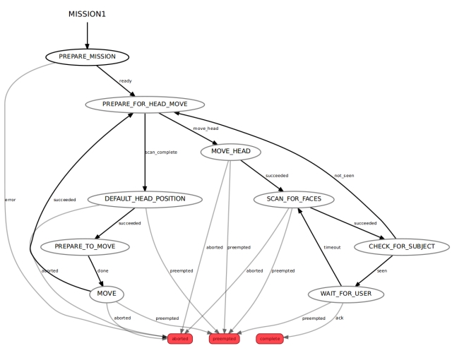
This mission is the culmination of our previous efforts. The entire code for this state machine is contained within the take_message_to.py file.
We enter this lower-level state machine through the PREPARE_MISSION state. The mission data passed to this state comprises the waypoint filename, the ID of the intended recipient, and the message to be delivered. These parameters are separated by the '|' character, so the first step is to split the data into its three constituent parts. The state machine then loads the waypoint file and, since we're navigating autonomously, ensures that the LIDAR is enabled. If the file is successfully opened and the waypoints are read, the state machine transitions to the PREPARE_FOR_HEAD_MOVE state. Conversely, if an error occurs, the mission is aborted, and the state machine returns to the higher-level root state machine.
Mission 4 - "Return to Base"
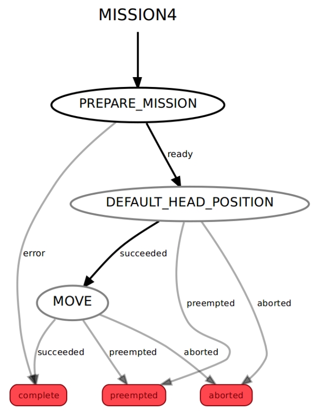
The entire code for this state machine is housed within the go_home.py file.
We access this lower-level state machine through the PREPARE_MISSION state. The mission data passed to this state includes the filename of the waypoints. The state machine loads the specified waypoint file, creates a navigation goal for the home waypoint, and enables the LIDAR to facilitate autonomous navigation. If the file is successfully read and the home waypoint is identified, the state machine transitions to the DEFAULT_HEAD_POSITION state. Conversely, if an error occurs during the process, the state machine returns to the higher-level root state machine.
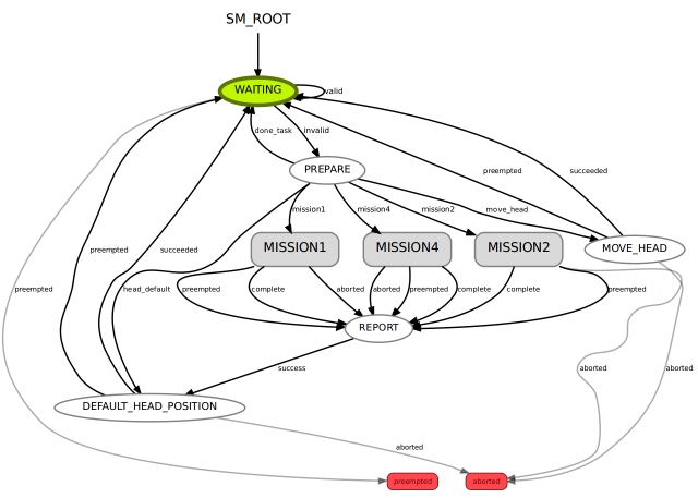
Modifications to the Root State Machine
To complete the integration of the new missions, we need to make some adjustments to the EaseRobot_missions_node.py file, which houses the root state machine. This involves incorporating the lower-level state machines as individual states.
We've already implemented code to return the default head position, but since we've added a job to set the head to a user-input angle, we need to define this position. This requires minor changes to the EaseRobot_missions_node.py file to accommodate this functionality.
The MissionsHelper class constructor now includes code to read the angle used for the user input position from the parameter server, using radians for angle values.
self.__user_input_position_pan = rospy.get_param("head/user_position/pan", 0.0)
self.__user_input_position_tilt = rospy.get_param("head/user_position/tilt", -0.5)
The class also includes a new function to return these values.
def UserInputPosition(self):
return self.__user_input_position_pan, self.__user_input_position_tilt
The PREPARE state of the root state machine now needs to include code not only to set the user input angle when requested but also to transition to the new lower-level state machines if requested. The complete code for the PREPARE state is shown below.
# The PREPARE state
class Prepare(State):
def init(self, helper_obj):
State.init(self, outcomes=['mission1','mission2',
'mission4','done_task','head_default','move_head'],
input_keys=['mission'],
output_keys=['mission_data','start','user_data_absolute',
'user_data_pan','user_data_tilt'])
self.__helper_obj = helper_obj

def execute(self, userdata):
    # Based on the userdata, either change state to the required mission or
    # carry out a single job
    retVal = 'done_task';

    # Split into parameters using '^' as the delimiter
    parameters = userdata.mission.split("^")

    if parameters[0] == 'M1':
        # Mission 1: search for a known person and deliver a message
        userdata.mission_data = parameters[1]
        retVal ='mission1'
    elif parameters[0] == 'M2':
        # Mission 2: scan for faces and greet those known
        userdata.start = True
        retVal ='mission2'
    elif parameters[0] == 'M4':
        # Mission 4: go home
        userdata.mission_data = parameters[1]
        retVal ='mission4'
    elif parameters[0] == 'J1':
        # Simple Job 1: play a supplied wav file and move the face lips
        self.__helper_obj.Wav(parameters[1], parameters[2])
    elif parameters[0] == 'J2':
        # Simple Job 2: speak the supplied text and move the face lips
        self.__helper_obj.Speak(parameters[1], parameters[2])
    elif parameters[0] == 'J3':
        # Simple Job 3: move the head/camera
        if 'c' in parameters[1]:
            # Move to default position
            retVal = 'head_default'
        elif 'i' in parameters[1]:
            # Move to user input position
            pan_position, tilt_position = self.__helper_obj.UserInputPosition()
            userdata.user_data_absolute = True
            userdata.user_data_pan = pan_position
            userdata.user_data_tilt = tilt_position
            retVal ='move_head'
        else:
            relative_request_pan, relative_request_tilt =
                 self.__helper_obj.CameraManualMove(parameters[1]+parameters[2])
            userdata.user_data_absolute = False
            userdata.user_data_pan = relative_request_pan
            userdata.user_data_tilt = relative_request_tilt
            retVal ='move_head'
    elif parameters[0] == 'J4':
        # Simple job to toggle the LIDAR on/off
        self.__helper_obj.ToggleLidar()

    return retVal
The remaining changes involve adding the new lower-level state machines to the root state machine in the RodneyMissionNode class.
This is an example of adding a new state machine to the root:
# Create a sub-state machine for mission 1 - take a message to
self.__sm_mission1 = missions_lib.Mission1StateMachine(self.__missions_helper)
Now add the sub-state machine for mission 1 to the top-level one
StateMachine.add('MISSION1',
self.__sm_mission1,
transitions={'complete':'REPORT','preempted':'REPORT','aborted':'REPORT'})
We must also make a call to preempt the lower-level state machine when a message to cancel a mission is received. The CancelCallback function now looks like this:
# Callback for cancel mission message
def CancelCallback(self, data):
# If a sub-state machine for a mission is running, request it be preempted
if self.__sm_mission1.is_running():
self.__sm_mission1.request_preempt()
elif self.__sm_mission2.is_running():
self.__sm_mission2.request_preempt()
elif self.__sm_mission4.is_running():
self.__sm_mission4.request_preempt()
Hardware Components of EaseRobot
For a detailed understanding of the circuitry, a comprehensive circuit diagram is provided in the diagrams zip folder. Additionally, a visual representation of the nodes and topics is available in the rqt_graph image, also included in the zip folder.
A thorough list of materials used in the project so far can be accessed here.
In the first part of this tutorial, I mentioned the Ubiquity Robot Image, which is utilized on the Raspberry Pi.
Summary
As we near the completion of our initial vision for EaseRobot, this final installment will focus on the following key objectives:
- Web-based Mission Assignment: We will explore how to assign missions and mission data through a web browser, thereby fulfilling Design Goal 6.
- Automated Greeting Mission: We will configure the robot to execute Mission 2, the greeting mission, upon startup.
- Self-Localization: We will investigate the possibility of enabling the robot to perform a self-localization maneuver. Accessing the Code
The current version of the code under development is included in the source zip file.