The EaseRobot Series 6: Building an Autonomous House Bot with ROS
Introduction
The EaseRobot project aims to create an autonomous house-bot using the Robot Operating System (ROS). This article marks the sixth installment in our ongoing series documenting this project.
Background
In the initial installment, we outlined our mission and broke it down into several design goals to manage the complexity.
The mission, inspired by the article "Let's Build a Robot!", was to create a robot that could relay messages within a household. The concept involved the robot recognizing family members and delivering messages, such as reminders to pick someone up from a station at a specific time.
The design goals were as follows:
- Enable the robot to use a camera to search for faces, identify people, and display messages.
- Incorporate facial expression recognition and speech synthesis for message delivery.
- Implement remote control locomotion via a keyboard or joystick.
- Add a laser range finder or similar sensor to assist with navigation.
- Achieve autonomous movement.
- Develop a system for task assignment and completion notifications.
In the previous segment, we achieved motor control and odometry feedback, fulfilling Design Goal 3. This segment focuses on integrating a spinning LIDAR (Light Detection and Ranging) to achieve Design Goal 4 and enhancing odometry with an Inertial Measurement Unit (IMU). Additionally, we'll replace the Arduino Nano with a Teensy 3.5.
Adding a LIDAR
Autonomous navigation in ROS typically involves subscribing to the /scan and /tf topics. The /tf topic provides the odom transform, which we started broadcasting in the previous segment using the ekf_localization_node. The /scan topic contains data from a laser scanning device.
High-end 360-degree LIDAR systems are used in autonomous vehicles, but for our indoor robot, a more affordable option like the Slamtec RPLidar A1 is suitable. Priced around £100 (GBP), this device offers a 12-meter range, 360-degree scan, and communicates via a serial interface. Moreover, Slamtec provides a ROS node available on their GitHub, allowing us to easily integrate the RPLidar with our robot.
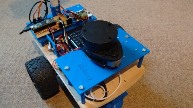
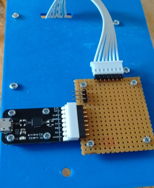
I purchased the RPLidar Development Kit, which includes a USB serial device and cable for connection. The device supplies 5V to both the LIDAR motor and core and features a PWM input to control motor speed. To balance power distribution, I chose to supply power to the motor and core separately, using a simple breakout board. The USB serial device is powered by the Raspberry Pi via USB.
For those following from the beginning, you might notice an issue: the robot's neck obstructs the LIDAR's laser, causing constant detection in its 360-degree field. To address this, we'll use the LaserScanAngularBoundsFilter from the ROS laser_filters package to exclude the neck area by filtering out 10 degrees on either side of the 180-degree mark.
Configuring the LIDAR
We'll modify the rodney and rodney_missions packages from previous segments to include the RPLidar. The laser_filter node will be launched from our rodney.launch file, requiring a configuration file loaded into the ROS parameter server.
Create laser_filter_config.yaml in the rodney/config folder with the following content:
scan_filter_chain:
- name: angle
  type: laser_filters/LaserScanAngularBoundsFilter
  params:
    lower_angle: -2.96706
    upper_angle: 2.96706
The angles are in radians, limiting the field of view to 0 to -170 and 0 to +170 degrees.
Next, add the following to rodney.launch in the rodney/launch folder:
<node pkg="laser_filters" type="scan_to_scan_filter_chain" name="scan_to_scan_filter_chain" output="screen">
  <rosparam command="load" file="$(find rodney)/config/laser_filter_config.yaml"/>
  <remap from="scan" to="scan_filter_input"/>
  <remap from="scan_filtered" to="scan"/>
</node>
This remaps the output topic of the node from scan_filtered to scan.
Launching the RPLidar Node
To launch the RPLidar node, we need to handle the device identification. Linux identifies the serial device as /dev/ttyUSBn, which can be ambiguous if multiple devices are connected. We resolve this by creating udev rules to set symbolic links.
Create rodney_udev.rules in the rodney/scripts folder:
# Set the udev rules.
#
# Arduino Nano
KERNEL=="ttyUSB*", ATTRS{idVendor}=="1a86", ATTRS{idProduct}=="7523", MODE:="0777", SYMLINK+="nano"
#
# Teensy
KERNEL=="ttyACM*", ATTRS{idVendor}=="16c0", ATTRS{idProduct}=="0483", MODE:="0777", SYMLINK+="teensy"
#
# RPLidar
KERNEL=="ttyUSB*", ATTRS{idVendor}=="10c4", ATTRS{idProduct}=="ea60", MODE:="0777", SYMLINK+="rplidar"
Copy this file to the /etc/udev/rules.d folder on the Raspberry Pi using a sudo command or the provided create_udev_rules.sh script.
Add the command to launch the RPLidar node to rodney.launch:
<node pkg="rplidar_ros" type="rplidarNode" name="rplidar_node" output="screen">
  <param name="serial_port" type="string" value="/dev/rplidar"/>
  <param name="serial_baudrate" type="int" value="115200"/>
  <param name="frame_id" type="string" value="laser"/>
  <remap from="scan" to="scan_filter_input"/>
</node>
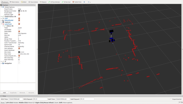
We'll build and run the code in the "Using the Code" section later, but the image below shows the laser scan message visualized in rviz.
Integrating an Inertial Measurement Unit (IMU)
Background
In part 5, we began broadcasting raw odometry data derived from the motor encoders and introduced the ekf_localization_node, which we planned to use for fusing raw odometry with IMU data to enhance the robot's odometry accuracy.
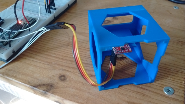
For this segment, we'll integrate a SparkFun MPU-9250 breakout board as our IMU.
Connecting the IMU
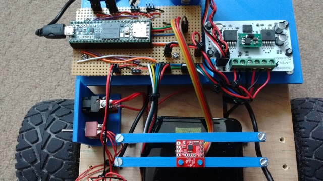
Instead of connecting the IMU directly to the Raspberry Pi, we'll link it to the microcontroller. Given that the Arduino Nano's memory is nearly maxed out, we need a more robust solution. We could either add a second Nano or switch to a larger Arduino board. However, I've decided to replace the Nano with a Teensy 3.5. The Teensy 3.5 is not only faster and has more memory than an Arduino but is also compatible with Arduino software and libraries. You can use a plugin to continue developing with the Arduino IDE. I chose the Teensy 3.5 because, unlike the Teensy 3.6, its digital inputs are 5V tolerant.
Below is an image showing the IMU (MPU-9250 breakout board) at the bottom and the Teensy at the top left.
Updating the Arduino Sketch
With the Teensy's increased speed, we can also increase the baud rate of the serial interface to the Raspberry Pi. As the project progresses, we may need to send larger messages between the Teensy and the Pi. To adjust the buffer sizes and baud rate, modifications to the ros.h and ArduinoHardware.h files in the ROS serial library are necessary. Instead of directly changing the library files, which would result in losing changes upon recompilation, I've recreated these files within the sketch folder.
The sketch retains the code for the servos and hall sensors but now includes IMU functionality.
Setup Function Changes
In the setup function, we ensure communication with the IMU and call setup procedures from the SparkFun MPU-9250 9 DOF IMU Breakout library, which I installed using the Arduino IDE Library Manager. Note that we also set up the magnetometer, even though we aren't currently broadcasting magnetometer data on any topic. The onboard LED is now only turned on if the IMU setup is successful.
Loop Function Changes
I've added code to log a message if the IMU setup fails since log calls made in the setup part of the sketch often don't get logged. During each loop iteration, we check if the IMU registers contain new data; if they do, we read the accelerometer, gyro, and magnetometer data. If it's time to publish the IMU data, we create a sensor_msgs/Imu message and broadcast it on the imu/data_raw topic.
Here's the updated rodney_control.ino:
#include <PWMServo.h> // Use PWMServo on Teensy
#include <MPU9250.h>

// Use "ros.h" not <ros.h> so that by using our local version
// we can increase/decrease buffer size if required and
// increased the baud rate on faster boards.
#include "ros.h"
#include <servo_msgs/servo_array.h>
#include <tacho_msgs/tacho.h>
#include <sensor_msgs/Imu.h>
#include <sensor_msgs/MagneticField.h>

void servo_cb( const servo_msgs::servo_array& cmd_msg);
void WheelSpeed0();
void WheelSpeed1();

#define LED_PIN 13  // Onboard LED

#define GEAR_BOX_COUNTS_PER_REV 1440.0f

// Define the period in milliseconds between tacho messages
#define TACHO_PERIOD_MS 50  // Publish at 20Hz

// Define the PWM pins that the other servos are connected to
#define SERVO_0 23
#define SERVO_1 22
#define SERVO_2 21
#define SERVO_3 20

// Define pins used for two Hall sensors
#define ENCODER0_PINA 0  // Interrupt
#define ENCODER0_PINB 1  // Digital pin
#define ENCODER1_PINA 3  // Interrupt
#define ENCODER1_PINB 4  // Digital pin

PWMServo  servo0;
PWMServo  servo1;
PWMServo  servo2;
PWMServo  servo3;

#define G_TO_MS2 9.80665

#define I2Cclock 400000
#define I2Cport Wire
#define MPU9250_ADDRESS MPU9250_ADDRESS_AD0
MPU9250 myIMU(MPU9250_ADDRESS, I2Cport, I2Cclock);

tacho_msgs::tacho tachoMsg;
sensor_msgs::Imu  imuMsg;

ros::NodeHandle nh;

ros::Publisher tachoPub("tacho", &tachoMsg);
ros::Publisher imuPub("imu/data_raw", &imuMsg);
ros::Subscriber<servo_msgs::servo_array> subServo("servo", servo_cb);

bool  imuTestPassed;
byte  encoder0PinALast;
byte  encoder1PinALast;
volatile int encoder0Count; // Number of pulses
volatile int encoder1Count; // Number of pulses
volatile boolean encoder0Direction; //Rotation direction
volatile boolean encoder1Direction; //Rotation direction
unsigned long publisherTime;
unsigned long currentTime;
unsigned long lastTime;
char imu_link[] = "imu";

void setup()
{
  Wire.begin();

  nh.initNode();
  nh.advertise(tachoPub);
  nh.advertise(imuPub);
  nh.subscribe(subServo);

  // Attach servos
  servo0.attach(SERVO_0); //attach it to the pin
  servo1.attach(SERVO_1);
  servo2.attach(SERVO_2);
  servo3.attach(SERVO_3);
  servo0.write(90);
  servo1.write(120);
  servo2.write(90);
  servo3.write(90);

  encoder0Direction = true;   // default is forward
  encoder1Direction = true;
  encoder0Count = 0;
  encoder1Count = 0;

  pinMode(ENCODER0_PINB, INPUT);
  pinMode(ENCODER1_PINB, INPUT);

  // Attach the interrupts for the Hall sensors
  attachInterrupt(digitalPinToInterrupt(ENCODER0_PINA), WheelSpeed0, CHANGE);
  attachInterrupt(digitalPinToInterrupt(ENCODER1_PINA), WheelSpeed1, CHANGE);

  imuTestPassed = true;

  // Read the WHO_AM_I register of the IMU, this is a good test of communication
  byte c = myIMU.readByte(MPU9250_ADDRESS, WHO_AM_I_MPU9250);

  if(c == 0x71) // WHO_AM_I should always be 0x71
  {
    // Start by performing self test
    myIMU.MPU9250SelfTest(myIMU.selfTest);

    for(int i = 0; i < 6; i++)
    {
      if(abs(myIMU.selfTest[i]) > 14.0f)
      {
        imuTestPassed = false;
      }
    }

    // Calibrate gyro and accelerometers, load biases in bias registers
    myIMU.calibrateMPU9250(myIMU.gyroBias, myIMU.accelBias);

    // Initialize device for active mode read of acclerometer, gyroscope, and temperature
    myIMU.initMPU9250();

    // Read the WHO_AM_I register of the magnetometer, this is a good test of communication
    byte d = myIMU.readByte(AK8963_ADDRESS, WHO_AM_I_AK8963);

    if(d == 0x48)
    {
      // Get magnetometer calibration from AK8963 ROM
      // Initialize device for active mode read of magnetometer
      myIMU.initAK8963(myIMU.factoryMagCalibration);

      // Get sensor resolutions, only need to do this once
      myIMU.getAres();
      myIMU.getGres();
      myIMU.getMres();
    }
    else
    {
      imuTestPassed = false;
    }
  }
  else
  {
    imuTestPassed = false;
  }

  if(imuTestPassed == true)
  {
    // Turn on the onboard LED to show we are running
    pinMode(LED_PIN, OUTPUT);
    digitalWrite(LED_PIN, HIGH);
  }
}

void loop()
{
  static bool setup = false;

  if(setup == false)
  {
    // Log only gets reported in loop
    nh.loginfo("Teensy code started");

    if(imuTestPassed == false)
    {
      nh.loginfo("IMU self test failed");
    }

    setup = true;
  }

  // Is it time to publish the tacho message
  if(millis() > publisherTime)
  {
    float deltaTime;

    currentTime = micros();
    deltaTime = (float)(currentTime - lastTime)/1000000.0;

    // Right wheel speed
    tachoMsg.rwheelrpm =
         (((((float)encoder0Count)/2.0f)/deltaTime)/GEAR_BOX_COUNTS_PER_REV)*60.0f;
    encoder0Count = 0;

    // Left wheel speed
    tachoMsg.lwheelrpm =
         (((((float)encoder1Count)/2.0f)/deltaTime)/GEAR_BOX_COUNTS_PER_REV)*60.0f;
    encoder1Count = 0;

    lastTime = currentTime;

    tachoPub.publish(&tachoMsg);
    publisherTime = millis() + TACHO_PERIOD_MS;
  }

  // IMU
  if(imuTestPassed == true)
  {
    // Check to see if all data registers have new data
    if (myIMU.readByte(MPU9250_ADDRESS, INT_STATUS) & 0x01)
    {
      myIMU.readAccelData(myIMU.accelCount);  // Read the x/y/z adc values

      // Now we'll calculate the accleration value into actual g's
      // This depends on scale being set
      myIMU.ax = (float)myIMU.accelCount[0] * myIMU.aRes;
      myIMU.ay = (float)myIMU.accelCount[1] * myIMU.aRes;
      myIMU.az = (float)myIMU.accelCount[2] * myIMU.aRes;

      myIMU.readGyroData(myIMU.gyroCount);  // Read the x/y/z adc values

      // Calculate the gyro value into actual degrees per second
      // This depends on scale being set
      myIMU.gx = (float)myIMU.gyroCount[0] * myIMU.gRes;
      myIMU.gy = (float)myIMU.gyroCount[1] * myIMU.gRes;
      myIMU.gz = (float)myIMU.gyroCount[2] * myIMU.gRes;

      myIMU.readMagData(myIMU.magCount);  // Read the x/y/z adc values

      // Reading mag data but not currently publishing it

      // Calculate the magnetometer values in milliGauss
      // Include factory calibration per data sheet and user environmental corrections
      // Get actual magnetometer value, this depends on scale being set
      myIMU.mx = (float)myIMU.magCount[0] * myIMU.mRes
                 * myIMU.factoryMagCalibration[0] - myIMU.magBias[0];
      myIMU.my = (float)myIMU.magCount[1] * myIMU.mRes
                 * myIMU.factoryMagCalibration[1] - myIMU.magBias[1];
      myIMU.mz = (float)myIMU.magCount[2] * myIMU.mRes
                 * myIMU.factoryMagCalibration[2] - myIMU.magBias[2];
    }

    // Is it time to publish IMU data
    myIMU.delt_t = millis() - myIMU.count;
    if (myIMU.delt_t > 50)
    {
      // IMU
      imuMsg.header.frame_id = imu_link;
      imuMsg.header.stamp = nh.now();

      // We are not providing orientation so the
      // first element of the this matrix should be -1
      imuMsg.orientation_covariance[0] = -1;

      imuMsg.angular_velocity.x = myIMU.gx * DEG_TO_RAD;
      imuMsg.angular_velocity.y = myIMU.gy * DEG_TO_RAD;
      imuMsg.angular_velocity.z = myIMU.gz * DEG_TO_RAD;

      // angular velocity covariance
      imuMsg.angular_velocity_covariance[0] = 0.003;
      imuMsg.angular_velocity_covariance[4] = 0.003;
      imuMsg.angular_velocity_covariance[8] = 0.003;

      imuMsg.linear_acceleration.x = myIMU.ax * G_TO_MS2;
      imuMsg.linear_acceleration.y = myIMU.ay * G_TO_MS2;
      imuMsg.linear_acceleration.z = myIMU.az * G_TO_MS2;

      // linear acceleration covariance
      imuMsg.linear_acceleration_covariance[0] = 0.1;
      imuMsg.linear_acceleration_covariance[4] = 0.1;
      imuMsg.linear_acceleration_covariance[8] = 0.1;

      imuPub.publish(&imuMsg);

      myIMU.count = millis();
    }
  }

  nh.spinOnce();
}

// Callback for when servo array message received
void servo_cb( const servo_msgs::servo_array& cmd_msg)
{
  /* Which servo to drive */
  switch(cmd_msg.index)
  {
    case 0:
      servo0.write(cmd_msg.angle); //set servo 0 angle, should be from 0-180
      break;

    case 1:
      servo1.write(cmd_msg.angle); //set servo 1 angle, should be from 0-180
      break;

    case 2:
      servo2.write(cmd_msg.angle); //set servo 2 angle, should be from 0-180
      break;

    case 3:
      servo3.write(cmd_msg.angle); //set servo 3 angle, should be from 0-180
      break;

    default:
      nh.logdebug("Error incorrect servo index");
      break;
  }
}

// ISR
void WheelSpeed0()
{
  int state = digitalRead(ENCODER0_PINA);

  if((encoder0PinALast == LOW) && (state == HIGH))
  {
    int val = digitalRead(ENCODER0_PINB);

    if(val == LOW && encoder0Direction)
    {
      encoder0Direction = false; // Reverse
    }
    else if (val == HIGH && !encoder0Direction)
    {
      encoder0Direction = true; // Forward
    }
  }

  encoder0PinALast = state;

  if(!encoder0Direction)
  {
    encoder0Count++;
  }
  else
  {
    encoder0Count--;
  }
}

// ISR
void WheelSpeed1()
{
  int state = digitalRead(ENCODER1_PINA);

  if((encoder1PinALast == LOW) && (state == HIGH))
  {
    int val = digitalRead(ENCODER1_PINB);

    if(val == LOW && encoder1Direction)
    {
      encoder1Direction = false; // Reverse
    }
    else if (val == HIGH && !encoder1Direction)
    {
      encoder1Direction = true; // Forward
    }
  }

  encoder1PinALast = state;

  if(!encoder1Direction)
  {
    encoder1Count++;
  }
  else
  {
    encoder1Count--;
  }
}
With these changes, the Teensy 3.5 will handle the IMU data and communicate efficiently with the Raspberry Pi, enhancing the robot's overall performance and sensor integration.
Here's the ros.h and ArduinoHardware.h files in the required format:
// ros.h

#ifndef _ROS_H_
#define _ROS_H_

#include <dummy.h>
#include <ros/node_handle.h>
#include "ArduinoHardware.h"

namespace ros
{

#if defined(__MK64FX512__) || defined(__MK66FX1M0__)
  // Teensy 3.5 or 3.6
  typedef NodeHandle_<ArduinoHardware, 25, 25, 512, 512> NodeHandle;
#elif defined(__AVR_ATmega328P__)
  // Arduino Nano
  // 10 publishers, 15 subscribers, 128 bytes input buffer and 256 bytes output buffer
  typedef NodeHandle_<ArduinoHardware, 10, 15, 128, 256> NodeHandle;
#else
  typedef NodeHandle_<ArduinoHardware> NodeHandle; // default 25, 25, 512, 512
#endif
}

#endif
// ArduinoHardware.h

#ifndef ROS_ARDUINO_HARDWARE_H_
#define ROS_ARDUINO_HARDWARE_H_

#if ARDUINO >= 100
  #include <Arduino.h>  // Arduino 1.0
#else
  #include <WProgram.h>  // Arduino 0022
#endif

#if defined(__MK20DX128__) || defined(__MK20DX256__) ||
    defined(__MK64FX512__) || defined(__MK66FX1M0__) || defined(__MKL26Z64__)
  #if defined(USE_TEENSY_HW_SERIAL)
    #define SERIAL_CLASS HardwareSerial // Teensy HW Serial
  #else
    #include <usb_serial.h>  // Teensy 3.0 and 3.1
    #define SERIAL_CLASS usb_serial_class
  #endif
#elif defined(_SAM3XA_)
  #include <UARTClass.h>  // Arduino Due
  #define SERIAL_CLASS UARTClass
#elif defined(USE_USBCON)
  // Arduino Leonardo USB Serial Port
  #define SERIAL_CLASS Serial_
#elif (defined(__STM32F1__) && !(defined(USE_STM32_HW_SERIAL))) || defined(SPARK)
  // Stm32duino Maple mini USB Serial Port
  #define SERIAL_CLASS USBSerial
#else
  #include <HardwareSerial.h>  // Arduino AVR
  #define SERIAL_CLASS HardwareSerial
#endif

class ArduinoHardware {
  public:
#if defined(__MK64FX512__) || defined(__MK66FX1M0__)
    ArduinoHardware(SERIAL_CLASS* io , long baud = 500000) {
      iostream = io;
      baud_ = baud;
    }
    ArduinoHardware() {
#if defined(USBCON) && !(defined(USE_USBCON))
      /* Leonardo support */
      iostream = &Serial1;
#elif defined(USE_TEENSY_HW_SERIAL) || defined(USE_STM32_HW_SERIAL)
      iostream = &Serial1;
#else
      iostream = &Serial;
#endif
      baud_ = 500000;
    }
#else // Not a Teensy
    ArduinoHardware(SERIAL_CLASS* io , long baud = 57600) {
      iostream = io;
      baud_ = baud;
    }
    ArduinoHardware() {
#if defined(USBCON) && !(defined(USE_USBCON))
      /* Leonardo support */
      iostream = &Serial1;
#elif defined(USE_TEENSY_HW_SERIAL) || defined(USE_STM32_HW_SERIAL)
      iostream = &Serial1;
#else
      iostream = &Serial;
#endif
      baud_ = 57600;
    }
#endif // defined(__MK64FX512__) || defined(__MK66FX1M0__)
    ArduinoHardware(ArduinoHardware& h) {
      this->iostream = h.iostream;
      this->baud_ = h.baud_;
    }

    void setBaud(long baud) {
      this->baud_ = baud;
    }

    int getBaud() { return baud_; }

    void init() {
#if defined(USE_USBCON)
      // Startup delay as a fail-safe to upload a new sketch
      delay(3000);
#endif
      iostream->begin(baud_);
    }

    int read() { return iostream->read(); }
    void write(uint8_t* data, int length) {
      for (int i = 0; i < length; i++)
        iostream->write(data[i]);
    }

    unsigned long time() { return millis(); }

  protected:
    SERIAL_CLASS* iostream;
    long baud_;
};

#endif
With these configurations, your Teensy microcontroller will effectively handle higher baud rates and larger message sizes, optimizing communication between the Teensy and Raspberry Pi for your ROS-enabled house-bot project.
Serial Node Baud Rate
Here is the updated rodney.launch file with the changes for setting the baud rate for the serial port:
<launch>
  <!-- Teensy.
       Use the defaults /dev/ttyACM0 (or teensy if dev rules updated) and 500000 -->
  <arg name="serial_port" default="/dev/teensy"/>
  <arg name="baud_rate" default="500000"/>

  <node pkg="rosserial_python" type="serial_node.py" name="serial_node" output="screen">
    <param name="port" value="$(arg serial_port)"/>
    <param name="baud" value="$(arg baud_rate)"/>
  </node>
</launch>
This configuration ensures that the ROS serial node on the Raspberry Pi is set to communicate at 500000 baud with the Teensy microcontroller.
IMU Calibration
When setting up the IMU, we can enhance the data quality by incorporating additional calibration beyond the factory settings. For this, we will use a ROS package available from a specific GitHub repository, which we will fork and modify slightly for our needs.
Initial Calibration
The package consists of two nodes. The first node computes accelerometer calibration parameters and saves them to a YAML file. This step needs to be done only once and requires placing the IMU in six specific orientations with precise positioning, best done before installing the IMU on the robot. The second node uses the calibration file to adjust an uncalibrated IMU topic, producing a calibrated IMU topic. This node can also optionally compute gyro biases at startup and subtract them from the raw data. Although the IMU setup in the sketch also performs this function, enabling this option provides better results.
Additionally, we will modify the second node to account for any slight misalignment of the IMU once installed on the robot, thus preventing accelerometer drift. This is particularly useful since Rodney is expected to operate on flat surfaces without inclines.
Calibration Setup
To perform the initial calibration, the IMU should be installed in a 3D-printed calibration cube. Although the cube was designed for a different IMU model, with some modifications, it can accommodate our IMU.
The calibration node do_calib expects IMU data to be published on the topic imu. The cal_imu.launch file is used to launch the ROS serial node and remap the topic:
<?xml version="1.0" ?>
<launch>

  <!-- Teensy.
       Use the defaults /dev/ttyACM0 (or teensy if dev rules updated) and 500000 -->
  <arg name="serial_port" default="/dev/ttyACM0"/>
  <arg name="baud_rate" default="500000"/>
  <node pkg="rosserial_python" type="serial_node.py"
  name="serial_node" output="screen">
    <param name="port" value="$(arg serial_port)"/>
    <param name="baud" value="$(arg baud_rate)"/>
    <remap from="/imu/data_raw" to="imu"/>
  </node>

  <!-- now "rosrun imu_calib do_calib" in a shell -->

</launch>
Once the serial node is running, execute the following command in another terminal to start the calibration process:
rosrun imu_calib do_calib
Follow the on-screen instructions to complete the calibration. After generating the calibration file, copy it to the rodney/config folder.
Node Modifications The changes to the imu_calib package are focused on the apply_calib.cpp and apply_calib.h files. Parameters are read from the parameter server to enable or disable functionality:
nh_private.param<bool>("null_accelerometer", null_accelerometer_, true);
nh_private.param<int>("null_accelerometer_samples", null_accelerometer_samples_, 100);
In the rawImuCallback function, code is added to calculate the mean accelerometer offsets at startup:
if(null_accelerometer_ == true)
{
  ROS_INFO_ONCE("Nulling accelerometer; do not move the IMU");

  // Recursively compute mean accelerometer measurements from corrected acceleration readings
  sensor_msgs::Imu corrected = *raw;
  accel_sample_count_++;

  calib_.applyCalib(raw->linear_acceleration.x,
               raw->linear_acceleration.y, raw->linear_acceleration.z,
               &corrected.linear_acceleration.x, &corrected.linear_acceleration.y,
               &corrected.linear_acceleration.z);

  accel_bias_x_ = ((accel_sample_count_ - 1) *
                    accel_bias_x_ + corrected.linear_acceleration.x) / accel_sample_count_;
  accel_bias_y_ = ((accel_sample_count_ - 1) *
                    accel_bias_y_ + corrected.linear_acceleration.y) / accel_sample_count_;
  accel_bias_z_ = ((accel_sample_count_ - 1) * accel_bias_z_ +
                   (corrected.linear_acceleration.z-9.80665)) / accel_sample_count_;

  if (accel_sample_count_ >= null_accelerometer_samples_)
  {
    ROS_INFO("Nulling accelerometers complete! (bias = [%.3f, %.3f, %.3f])",
              accel_bias_x_, accel_bias_y_, accel_bias_z_);
    null_accelerometer_ = false;
  }
}
These offsets are subtracted from the calibration-corrected values:
corrected.linear_acceleration.x -= accel_bias_x_;
corrected.linear_acceleration.y -= accel_bias_y_;
corrected.linear_acceleration.z -= accel_bias_z_;
Updating the Launch File
The following addition to the rodney.launch file launches the updated node and specifies the location of the calibration file:
<!-- Add calibration to raw imu data -->
<node pkg="imu_calib" type="apply_calib" name="imu_calib" output="screen">
  <param name="calib_file" value="$(find rodney)/config/imu_calib.yaml"/>
</node>
Data Fusion Configuration
The robot_localization.yaml file, found in the rodney/config folder, configures the data fusion process for the ekf_localization_node from the robot_localization package. This node combines IMU and raw odometry data to generate odometry data used by the navigation system.
The configuration matrix is structured as follows:
[ x position,     y position,     z position,
  roll,           pitch,          yaw,
  x velocity,     y velocity,     z velocity,
  roll velocity,  pitch velocity, yaw velocity,
  x acceleration, y acceleration, z, acceleration]
A "true" value in the matrix means the corresponding data will be used by the Extended Kalman Filter.
For the raw odometry data:
odom0_config: [false, false, false,
               false, false, false,
               true,  true,  false,
               false, false, true,
               false, false, false]
For the IMU data, two configurations can be tried:
- Using just the yaw velocity from the IMU:
imu0_config: [false, false, false,
              false, false, false,
              false, false, false,
              false, false, true,
              false, false, false]
- Including x and y velocities (ensure noise/error reduction):
imu0_config: [false, false, false,
              false, false, false,
              true, true, false,
              false, false, true,
              false, false, false]
Static Transforms
In the previous section, we introduced a static transform for the height of the robot base from the ground using a latched transform broadcast from the rodney.launch file:
<node pkg="tf2_ros" type="static_transform_publisher"
      name="base_footprint_broadcaster" args="0 0 0.09 0 0 0 /base_footprint /base_link"/>
With the addition of the LIDAR and IMU, we need to incorporate more static transforms. The measurements from the LIDAR need to be translated from its location to the center of the robot. Instead of adding multiple static transforms in the launch file, we'll write a single node to manage all the necessary static transforms.
Creating the Static Transform Broadcaster Node
In the rodney/src folder, add the static_broadcaster.py file. This Python script will create a node responsible for broadcasting the three static transforms, with the transforms being latched to ensure they are available to other nodes upon startup.
# Rodney robot static transform broadcaster

import sys
import rospy
import tf
import tf2_ros
import geometry_msgs.msg

def main(args):
    rospy.init_node('rodney_static_broadcaster', anonymous=False)
    rospy.loginfo("Rodney static broadcaster node started")

    broadcaster = tf2_ros.StaticTransformBroadcaster()

    # Static transform for the base_footprint to base_link
    st1 = geometry_msgs.msg.TransformStamped()
    st1.header.stamp = rospy.Time.now()
    st1.header.frame_id = "base_footprint"
    st1.child_frame_id = "base_link"
    st1.transform.translation.x = 0.0
    st1.transform.translation.y = 0.0
    st1.transform.translation.z = 0.09
    quat = tf.transformations.quaternion_from_euler(0.0, 0.0, 0.0)
    st1.transform.rotation.x = quat[0]
    st1.transform.rotation.y = quat[1]
    st1.transform.rotation.z = quat[2]
    st1.transform.rotation.w = quat[3]

    # Static transform for the base_link to laser
    st2 = geometry_msgs.msg.TransformStamped()
    st2.header.stamp = rospy.Time.now()
    st2.header.frame_id = "base_link"
    st2.child_frame_id = "laser"
    st2.transform.translation.x = 0.085
    st2.transform.translation.y = 0.0
    st2.transform.translation.z = 0.107
    quat = tf.transformations.quaternion_from_euler(0.0, 0.0, 0.0)
    st2.transform.rotation.x = quat[0]
    st2.transform.rotation.y = quat[1]
    st2.transform.rotation.z = quat[2]
    st2.transform.rotation.w = quat[3]

    # Static transform for the base_link to imu
    st3 = geometry_msgs.msg.TransformStamped()
    st3.header.stamp = rospy.Time.now()
    st3.header.frame_id = "base_link"
    st3.child_frame_id = "imu"
    st3.transform.translation.x = 0.0
    st3.transform.translation.y = 0.0
    st3.transform.translation.z = 0.058
    quat = tf.transformations.quaternion_from_euler(0.0, 0.0, 0.0)
    st3.transform.rotation.x = quat[0]
    st3.transform.rotation.y = quat[1]
    st3.transform.rotation.z = quat[2]
    st3.transform.rotation.w = quat[3]

    broadcaster.sendTransform([st1, st2, st3])

    # Static transforms are latched, so we only need to
Adding the Node to the Launch File
To ensure the node starts with the robot, add the following entry to the rodney.launch file:
<!-- Static transforms in the system -->
<node pkg="rodney" type="static_broadcaster.py" name="static_broadcaster_node"/>
By implementing this node, we streamline the process of broadcasting static transforms, making it easier to manage and extend in the future. This approach ensures that all necessary static transforms are available to any node that requires them, improving the robot's ability to accurately interpret sensor data relative to its frame of reference.
Updated Launch File
Here is the revised rodney.launch file, with the output="screen" parameter removed from nodes that are no longer under development or test to reduce the amount of log messages displayed in the terminal. This file also includes the new static transform broadcaster node and other updates mentioned in the previous sections.
<?xml version="1.0" ?>
<launch>
  <!-- Static transforms in the system -->
  <node pkg="rodney" type="static_broadcaster.py" name="static_broadcaster_node"/>

  <!-- Load each of the config files into the parameter server -->
  <rosparam command="load" file="$(find pan_tilt)/config/config.yaml"/>
  <rosparam command="load" file="$(find face_recognition)/config/config.yaml"/>
  <rosparam command="load" file="$(find head_control)/config/config.yaml"/>
  <rosparam command="load" file="$(find rodney_missions)/config/config.yaml"/>

  <!-- Launch the camera node from one of its launch files -->
  <include file="$(find raspicam_node)/launch/camerav2_1280x960.launch" />

  <!-- Start all the nodes that make up Rondey -->
  <!-- Starting with those written for the project -->
  <node pkg="pan_tilt" type="pan_tilt_node" name="pan_tilt_node"/>
  <node pkg="face_recognition" type="face_recognition_node.py" name="face_recognition_node"/>
  <node pkg="head_control" type="head_control_node" name="head_control_node"/>
  <node pkg="speech" type="speech_node" name="speech_node"/>
  <node pkg="rodney_missions" type="rodney_missions_node.py"
        name="rodney_missions" output="screen"/>
  <node pkg="rodney" type="rodney_node" name="rodney" output="screen">
    <rosparam command="load" file="$(find rodney)/config/config.yaml"/>
  </node>
  <node pkg="thunderborg" type="thunderborg_node.py" name="thunderborg_node">
    <rosparam command="load" file="$(find thunderborg)/config/config.yaml"/>
  </node>

  <!-- Teensy.
       Use the defaults /dev/ttyACM0 (or teensy if dev rules updated) and 500000 -->
  <arg name="serial_port" default="/dev/teensy"/>
  <arg name="baud_rate" default="500000"/>
  <node pkg="rosserial_python" type="serial_node.py" name="serial_node" output="screen">
    <param name="port" value="$(arg serial_port)"/>
    <param name="baud" value="$(arg baud_rate)"/>
  </node>

  <!-- The RPLidar and laser filter node
       Have created symbolic link for /dev/ttyUSBn to be rplidar -->
  <node pkg="rplidar_ros" type="rplidarNode" name="rplidar_node" output="screen">
    <param name="serial_port" type="string" value="/dev/rplidar"/>
    <param name="serial_baudrate" type="int" value="115200"/>
    <param name="frame_id" type="string" value="laser"/>
    <remap from="scan" to="scan_filter_input"/>
  </node>
  <node pkg ="laser_filters" type="scan_to_scan_filter_chain"
        name="scan_to_scan_filter_chain" output="screen">
    <rosparam command="load" file="$(find rodney)/config/laser_filter_config.yaml"/>
    <remap from="scan" to="scan_filter_input"/>
    <remap from="scan_filtered" to="scan"/>
  </node>

  <!-- The robot face -->
  <node pkg="homer_robot_face" type="RobotFace" name="RobotFace"/>

  <!-- Add calibration to raw imu data -->
  <node pkg="imu_calib" type="apply_calib" name="imu_calib" output="screen">
    <param name="calib_file" value="$(find rodney)/config/imu_calib.yaml"/>
  </node>

  <!-- Node to fuse motor encoder and IMU data for odom -->
  <node pkg="robot_localization" type="ekf_localization_node" name="ekf_localization_node">
    <remap from="odometry/filtered" to="odom"/>
    <rosparam command="load" file="$(find rodney)/config/robot_localization.yaml"/>
  </node>

</launch>
Code Improvements
I have implemented several subtle code refinements, primarily focused on enabling and disabling the LIDAR when the EaseRobot is in manual mode, as well as preventing uncontrolled robot movements during remote control.
Updates to the EaseRobot Missions Node
I have made subtle adjustments to this node, enabling it to control the LIDAR by starting and stopping the LIDAR motor. Although the request originates from the EaseRobot node, it is crucial that this node exercises control to ensure the LIDAR operates when autonomous navigation is requested in the future.
The motor startup and shutdown are accomplished via ROS service calls to the LIDAR node. The initial changes are found in the init function of the MissionsHelper class. We wait for the services to become available, create proxy calls to access the service, and then invoke the LidarEnable helper function to verify the LIDAR's current operational status.
# RPLidar services to start and stop the motor
rospy.wait_for_service('stop_motor')
rospy.wait_for_service('start_motor')
self.__rplidar_stop_motor_srv = rospy.ServiceProxy('stop_motor', std_srvs.srv.Empty)
self.__rplidar_start_motor_srv = rospy.ServiceProxy('start_motor', std_srvs.srv.Empty)
# LIDAR should be running but make sure
self.LidarEnable()
Next, I have added three helper functions to the MissionHelper class, which invoke the respective service and maintain a record of the LIDAR motor's current state.
# Function to enable the RPLidar
def LidarEnable(self):
    self.__rplidar_start_motor_srv()
    self.__lidar_on = True

# Function to disable the RPLidar
def LidarDisable(self):
    self.__rplidar_stop_motor_srv()
    self.__lidar_on = False

# Function to Toggle RPLidar on/off
def ToggleLidar(self):
    if(self.__lidar_on == True):
        self.LidarDisable()
    else:
        self.LidarEnable()
The final update involves modifying the Prepare class by introducing an additional elif statement within the execute function. This new condition checks if the received job identifier is 'J4', indicating a request to toggle the current state of the LIDAR.
elif parameters[0] == 'J4':
    # Toggle the LIDAR state
    self.__helper_obj.ToggleLidar()
These changes are part of ongoing enhancements to the EaseRobot project.
Updates to the EaseRobot Package
To enhance the functionality of the EaseRobot package, several key updates are planned for the rodney node. These changes aim to enable/disable the LIDAR using either the joystick or keyboard connected to the remote workstation during manual mode.
Additionally, a new issue has been identified where the robot continues using the last input velocities when the home network drops out temporarily during manual control. To address this, a new node named remote_heartbeat_node has been introduced in the rodney package. This node, running on the remote workstation, publishes a heartbeat message. The rodney node on the robot hardware now monitors this message: if the robot is in manual mode and the message isn't received for one second, velocities will automatically reset to zero.
Changes to rodney_node.cpp
To enable LIDAR control from the joystick, configure the appropriate button by adding the following line to the RodneyNode constructor.
nh_.param("/controller/buttons/lidar_enable", lidar_enable_select_, 2);
In the oystickCallback` function, incorporate the following conditional statement to toggle the LIDAR motor state when the corresponding joystick button is pressed:
// Button on controller selects to enable/disable the lidar function
if((manual_locomotion_mode_ == true) && (msg->buttons[lidar_enable_select_] == 1))
{
    std_msgs::String mission_msg;

    // Toggle the LIDAR on/off
    mission_msg.data = "J4";

    mission_pub_.publish(mission_msg);
    last_interaction_time_ = ros::Time::now();
}
Similarly, when the 'l' key is pressed on the keyboard, the motor state should be toggled. To achieve this, add the following "else if" construct to the keyboardCallBack function:
else if((msg->code == keyboard::Key::KEY_l) &&
       ((msg->modifiers & ~RodneyNode::SHIFT_CAPS_NUM_LOCK_) == 0))
{
    if(manual_locomotion_mode_ == true)
    {
        std_msgs::String mission_msg;

        // Toggle the LIDAR on/off
        mission_msg.data = "J4";

        mission_pub_.publish(mission_msg);
        last_interaction_time_ = ros::Time::now();
    }
}
remote_heartbeat_sub_ = nh_.subscribe
                        ("remote_heartbeat", 1, &RodneyNode::remHeartbeatCallback, this);
A callback function for when the message on this topic is received will store the time of the last message.
// Callback for remote heartbeat
void RodneyNode::remHeartbeatCallback(const std_msgs::Empty::ConstPtr& msg)
{
    // Remote heartbeat received store the time
    remote_heartbeat_time_ = ros::Time::now();
}
In the sendTwist function, it is essential to reset the velocities to zero if more than one second has elapsed since the last heartbeat message was received. The updated implementation of the sendTwist function is presented below:
void RodneyNode::sendTwist(void)
{
    geometry_msgs::Twist target_twist;

    // If in manual locomotion mode use keyboard or joystick data
    if(manual_locomotion_mode_ == true)
    {
        // Only allow stored keyboard or joystick values to set
        // the velocities if the remote heartbeat is running
        if((ros::Time::now() - remote_heartbeat_time_).toSec() < 1.0)
        {
            // Publish message based on keyboard or joystick speeds
            if((keyboard_linear_speed_ == 0) && (keyboard_angular_speed_ == 0))
            {
                // Use joystick values
                target_twist.linear.x = joystick_linear_speed_;
                target_twist.angular.z = joystick_angular_speed_;
            }
            else
            {
                // use keyboard values
                target_twist.linear.x = keyboard_linear_speed_;
                target_twist.angular.z = keyboard_angular_speed_;
            }
        }
        else
        {
            // Lost connection with remote workstation so zero the velocities
            target_twist.linear.x = 0.0;
            target_twist.angular.z = 0.0;
        }
    }
    else
    {
        // Use mission demands (autonomous)
        target_twist.linear.x = linear_mission_demand_;
        target_twist.angular.z = angular_mission_demand_;
    }

    // If not using the PID ramp to the target value.
    if (false == pid_enabled_)
    {
        ros::Time time_now = ros::Time::now();

        // Ramp towards are required twist velocities
        last_twist_ = rampedTwist(last_twist_, target_twist, last_twist_send_time_, time_now);

        last_twist_send_time_ = time_now;

        // Publish the Twist message using the ramp value
        twist_pub_.publish(last_twist_);
    }
    else
    {
        // Publish the Twist message using the target value
        twist_pub_.publish(target_twist);
    }
}
Next, we will create the remote_heartbeat_node.cpp file within the EaseRobot/src directory. Note that this node is designed to run on a remote workstation, allowing manual control of the robot, rather than on the robot's hardware itself. The purpose of this node is to simply broadcast the heartbeat message at a frequency of 5Hz.
// This heartbeat node is not to be run on the robot platform but on a remote worksation
// when either the keyboard or joystick nodes are being used to teleop the robot. If the
// message sent by this node is missed for 1 second, the robot will stop using the keyboard
// and joystick stored values to drive the motors.
#include <ros/ros.h>
#include <std_msgs/Empty.h>

int main(int argc, char **argv)
{
    ros::init(argc, argv, "remote_heartbeat");
    ros::NodeHandle n;

    ros::Publisher remote_heartbeat_pub = n.advertise<std_msgs::Empty>("remote_heartbeat", 1);

    std::string node_name = ros::this_node::getName();
    ROS_INFO("%s started", node_name.c_str());

    ros::Rate r(5); // 5Hz

    std_msgs::Empty beat;

    while(ros::ok())
    {
        remote_heartbeat_pub.publish(beat);

        ros::spinOnce();
        r.sleep();
    }

    return 0;
}
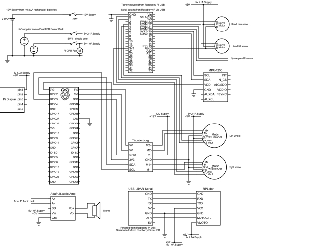
Robot Hardware
Summary
In this section, Design Goal 4 has been successfully achieved, and an IMU has been integrated to enhance odometry accuracy.
The upcoming article will focus on integrating packages that utilize LIDAR for autonomous navigation. This includes generating maps based on LIDAR and odometry transform data. We will utilize rviz to define target poses, enabling the robot to autonomously navigate to specified locations.