The EaseRobot Series 5: Building an Autonomous House Bot with ROS
Introduction
The EaseRobot Project is a hobbyist robotic project aimed at designing and building an autonomous house-bot using ROS (Robot Operating System). This article is the fifth in the series describing the project.
Background
In part 1, we defined the requirements for our robot by selecting our initial mission and breaking it down into several Design Goals to make it more manageable.
The mission was inspired by an article on building robots: "Let's build a robot!". The mission we chose was to enable the robot to recognize family members and act as a 'message taker and reminder'. For example, it could be instructed: "Robot, remind (PersonName) to pick me up from the station at 6pm". Even if the household member's phone is on silent or they are occupied, the robot could navigate the house, locate the person, and deliver the message.
The design goals identified for this mission are:
- Design Goal 1: Enable visual perception using a camera to detect faces and display messages for recognized individuals.
- Design Goal 2: Implement facial expression recognition and speech synthesis for effective communication.
- Design Goal 3: Implement locomotion control via remote keyboard and/or joystick.
- Design Goal 4: Integrate a laser range finder or similar sensor for navigation assistance.
- Design Goal 5: Achieve autonomous navigation capabilities.
- Design Goal 6: Implement task assignment and completion notification mechanisms.
Comparison: 2WD vs 4WD
In the early stages of developing EaseRobot, I initially envisioned it with four wheels and employing "Skid steering". Skid steering is advantageous for navigating rough terrain but consumes substantial power during turns. However, during initial trials, I noticed some unpredictability in turning behavior, likely due to the wide, knobby tires gripping tightly on the carpeted floor. Given that EaseRobot is designed for household use and doesn't require Mars-like terrain capabilities, I decided to simplify the design to two wheels and two passive casters, using "Differential drive". While simpler to implement, differential drive may not handle bumps and obstacles as effectively.
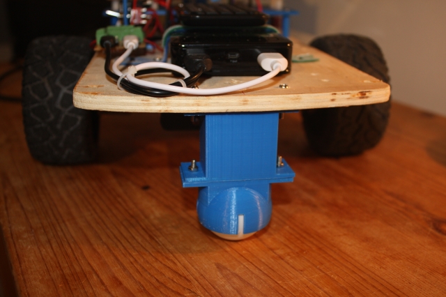
Initially, I used two furniture swivel casters for the passive wheels, but they didn't consistently align with the robot's intended direction, causing deviations from the desired path. Later on, I came across a 3D print design on Thingiverse that utilizes a table tennis ball as a caster. I customized this design by incorporating my own 3D printed spacer to adjust its height as needed. Despite lacking internal rollers found in commercial ball casters, this solution appears to meet EaseRobot's operational requirements effectively.
Motor Control Board Selection
The next critical decision in the design process was selecting a suitable control board to power the electric motors. Initially, I considered the L293D chip, as used in the PiRex project—a Raspberry Pi-based remote-controlled robot. Another option was the L298N motor driver board, known for its versatility. However, after careful evaluation, I opted for the Thunderborg from PiBorg. Despite being more expensive, this board offers higher power output and essential features such as under-voltage and short-circuit protection. Notably, it includes the capability to monitor battery voltage and features a safety mechanism that shuts down motors if communication with the controlling software is lost, preventing potential runaway scenarios.
Moreover, the Thunderborg integrates a 5V regulator, which will conveniently power the Raspberry Pi. Communication with the board utilizes an I2C link, facilitated by a library available for download from the PiBorg website. This library simplifies communication between the Raspberry Pi and Thunderborg, enabling straightforward motor control operations such as setting motor speeds with commands like TB.SetMotor1(0.5).
I will utilize the example code and library files provided in the PiBorg's zip package within my ROS node for seamless integration.
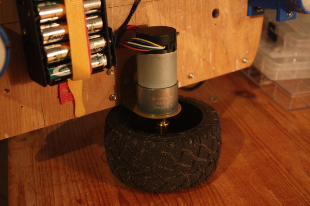
Geared Motors with Encoders
For the two electric motors, I have selected 12V geared motors equipped with a Hall effect sensor. These sensors will play a crucial role in our control strategy, particularly in implementing a PID controller to regulate the motor speed of each wheel. While the feedback from the Hall sensors is essential for PID functionality, their primary purpose will be to generate odometry data. This odometry information will be integrated with LIDAR data by the ROS navigation system, particularly when the robot operates in autonomous mode.
Code Development
In our next steps, we will focus on the code development for EaseRobot. This involves creating two new ROS packages and updating the existing easerobot package, particularly the Arduino sketch to handle signals from the Hall sensors.
tacho_msgs Package
The first new package, tacho_msgs, serves a straightforward purpose: defining a custom ROS message. This message will transmit RPM data from the Arduino node to the Raspberry Pi node controlling the motors. Here's an overview of the package structure:
- Package Structure:
-
tacho_msgs/msg/-
tacho.msg:float32 lwheelrpm # RPM of the left wheel float32 rwheelrpm # RPM of the right wheelThis message definition includes fields for the RPM of the left and right motors. -
launch/ test.launch: Launches the serial node for communication with Arduino during initial package testing.
thunderborg Node Package
The second new package, thunderborg, will function as the driver node for the Thunderborg controller. Additionally, it will generate raw odometry messages. Here's a breakdown of this package:
- Package Structure:
-
thunderborg/cfg/-
thunderborg.cfg: A Python script used by the dynamic reconfiguration server to adjust PID parameters dynamically. -
Other standard ROS package files for node configuration and management.
These packages lay the foundation for integrating motor control, RPM feedback via custom messages, and dynamic PID tuning capabilities using the Thunderborg controller within the ROS framework.
#!/usr/bin/env python
# Dynamic rconfiguration for Thunderborg node
PACKAGE = "thunderborg"

from dynamic_reconfigure.parameter_generator_catkin import *

gen = ParameterGenerator()

gen.add("p_param", double_t, 0, "P-Proportional", 0.5, 0, 5)
gen.add("i_param", double_t, 0, "I-Integral", 0.9, 0, 5)
gen.add("d_param", double_t, 0, "D-Derivative", 0.006, 0, 5)

gen.add("restore_defaults", bool_t, 0, "Restore to original configuration", False)

exit(gen.generate(PACKAGE, "thunderborg_node", "Thunderborg"))
In the previous sections of this guide, we utilized the dynamic reconfiguration server. For the PID controller, the default parameters are initially set as follows: 0.5 for the proportional parameter, 0.9 for the integral parameter, and 0.006 for the derivative parameter. To fine-tune the PID controller, you can use the rqt_reconfiguration application. Once you have determined the optimal values, you should update them in the config.yaml file, which is detailed below.
Within the config folder, there exists a file named config.yaml. This specific file is referenced by the launch file to initialize the designated parameters on the parameter server. This approach allows for convenient system configuration adjustments without necessitating code recompilation.
p_param: 0.5
i_param: 0.9
d_param: 0.006

pid:
  use_pid: true
  inertia_level: 0.1

wheels:
  distance: 0.242
  circumference: 0.317

speed:
  # Plot x=thunderborg value, y=m/s
  slope: 0.649776
  y_intercept: -0.0788956
  motor_diag_msg: false
The config.yaml file includes the following parameters for configuration:
p_parm: Proportional parameter for the PID controlleri_parm: Integral parameter for the PID controllerd_parm: Derivative parameter for the PID controllerpid/use_pid: When set to true, enables the PID controller for motor speed controlpid/inertia_level: Sets a threshold motor speed value below which the robot does not movewheels/distance: Distance in meters between the two wheelswheels/circumference: Circumference of the wheels in metersspeed/slope: Slope value of the velocity-to-motor-controller-value conversion graphspeed/y_intercept: Y-intercept value of the velocity conversion graphspeed/motor_diag_msg: If true, publishes diagnostic messages for each motor for testing purposes
The ROS node is located in the src subfolder, specifically in the file thunderborg_node.py. This node utilizes a library file named ThunderBorg.py, which resides in src/thunderborg_lib. Both the node and the library are implemented in Python, following the conventions of the PiBorg website's code.
Here's an overview of the ROS node:
The main routine initializes ROS for the node and instantiates ThunderBorgNode. It then enters a loop that continues until the node is shut down. This loop operates at a frequency of 20Hz and invokes several functions from ThunderBorgNode, which are detailed below:
- PublishStatus: Called at a rate of 1Hz.
- PublishOdom and RunPIDs: Called during each iteration of the 20Hz loop.
def main(args):
    rospy.init_node('thunderborg_node', anonymous=False)
    rospy.loginfo("Thunderborg node started")
    tbn = ThunderBorgNode()

    rate = rospy.Rate(RATE)

    status_time = rospy.Time.now()

    while not rospy.is_shutdown():

        if rospy.Time.now() > status_time:
            tbn.PublishStatus()
            status_time = rospy.Time.now() + rospy.Duration(1)

        # Publish ODOM data
        tbn.PublishOdom()

        # Run the PIDs
        tbn.RunPIDs()

        rate.sleep()


if __name__ == '__main__':
    main(sys.argv)
The ThunderBorgNode class initializes upon reading values from the parameter server. Default values are used if any parameters are missing.
If the /pid/use_pid parameter is true, the constructor instantiates two instances of the PID controller (one for each motor) using the simple-pid library.
Next, an instance of the communication class with the Thunderborg board is created, and communication at the specified I2C address is verified.
Several variables are initialized, including topics for publishing battery status (main_battery_status), odometry data (raw_odom), and optionally, diagnostic messages for motor 1 and motor 2 (motor1_diag and motor2_diag).
The node subscribes to two topics:
- cmd_vel: Published by the easerobot node from part 4, providing the required velocities for the robot.
- tacho: Provides RPM (Revolutions Per Minute) for each motor.
class ThunderBorgNode:
    def __init__(self):
        self.__setup = False
        # Read values from parameter server
        # Using '~private_name' will prefix the parameters with the node name given in launch file
        self.__use_pid = rospy.get_param('~pid/use_pid', False)
        self.__wheel_distance = rospy.get_param('~wheels/distance', 0.23)
        self.__wheel_circumference = rospy.get_param('~wheels/circumference', 0.34)
        self.__speed_slope = rospy.get_param('~speed/slope', 1.5)
        self.__speed_y_intercept = rospy.get_param('~speed/y_intercept', 0.4)
        self.__inertia = rospy.get_param('~pid/inertia_level', 0.0)
        self.__diag_msgs = rospy.get_param('~speed/motor_diag_msg', False)

        pid_p = rospy.get_param('~p_param', 0.0)
        pid_i = rospy.get_param('~i_param', 0.0)
        pid_d = rospy.get_param('~d_param', 0.0)

        if self.__use_pid == True:
            # Configure the PIDs.
            self.__pid1 = PID(pid_p, pid_i, pid_d, setpoint=0)
            self.__pid1.sample_time = 0.05
            # Limit the pid range. The PID will only work in positive values
            self.__pid1.output_limits = (self.__inertia, 1.0)

            self.__pid2 = PID(pid_p, pid_i, pid_d, setpoint=0)
            self.__pid2.sample_time = 0.05
            self.__pid2.output_limits = (self.__inertia, 1.0)

            # We call dynamic server here after the PIDs are set up
            # so the new PID values are set after the PIDs were created
            srv = Server(ThunderborgConfig, self.DynamicCallback)

        self.__thunderborg = thunderborg_lib.ThunderBorg()  # create the thunderborg object
        self.__thunderborg.Init()
        if not self.__thunderborg.foundChip:
            rospy.logdebug("ThunderBorg board not found")
        else:
            # Setup board to turn off motors if we don't send a message every 1/4 second
            self.__thunderborg.SetCommsFailsafe(True)

        # Motor velocity feedback values m/s
        self.__feedback_velocity_right = 0.0
        self.__feedback_velocity_left = 0.0

        # Last motor direction
        self.__fwd_right = True
        self.__fwd_left = True

        # Speed request in m/s
        self.__speed_wish_right = 0.0
        self.__speed_wish_left = 0.0

        # Publish topics
        self.__status_pub = rospy.Publisher("main_battery_status", BatteryState, queue_size=1)
        self.__odom_pub = rospy.Publisher("raw_odom", Odometry, queue_size=50)
        if self.__diag_msgs == True:
            self.__diag1_pub = rospy.Publisher("motor1_diag", Vector3, queue_size=1)
            self.__diag2_pub = rospy.Publisher("motor2_diag", Vector3, queue_size=1)

        # ODOM values
        self.__odom_x = 0.0
        self.__odom_y = 0.0
        self.__odom_th = 0.0
        self.__last_odom_time = rospy.Time.now()

        # Subscribe to topics
        self.__vel_sub = rospy.Subscriber("cmd_vel",Twist, self.VelCallback)
        self.__feedback_sub = rospy.Subscriber("tacho", tacho, self.TachoCallback)
The function `DynamicCallbackis invoked during initialization and when PID parameters are modified. Its primary role is to update the PID parameters of two controllers based on dynamic reconfiguration. Upon the initial call, the current configuration is saved as the default setting. To revert to this default setup, users can click the "Restore to original configuration" checkbox on the reconfiguration server.
# Dynamic reconfiguration of PID settings
def DynamicCallback(self, config, level):
    # Store configuration on first call
    if not self.__setup:
        self.__default_config = config
        self.__setup = True
    else:
        # Restore configuration if requested
        if config.restore_defaults:
            config = self.__default_config
            config.restore_defaults = False

        # Update PID parameters
        self.__pid1.tunings = (config.p_param, config.i_param, config.d_param)
        self.__pid2.tunings = (config.p_param, config.i_param, config.d_param)

    return config
The MotorSetting function assists in converting a desired motor velocity from meters per second into a format compatible with the Thunderborg board (ranging from 0.0 to 1.0). This function employs a linear transformation based on slope and y-intercept values extracted from a configuration file to determine motor settings.
# Convert velocity to Thunderborg motor setting
def MotorSetting(self, vel):
    if vel == 0.0:
        setting = 0.0
    else:
        setting = (abs(vel) - self.__speed_y_intercept) / self.__speed_slope
        if vel < 0.0:
            setting = -setting
    return setting
The VelCallback function is triggered upon receiving messages on the cmd_vel topic, extracting linear and angular velocities. It calculates required speeds for both left and right motors, utilizing the MotorSetting function to derive Thunderborg board-compatible motor values. Depending on whether the PID controller is active, these motor values are either used directly to set the set point for the PID controllers or directly passed to the Thunderborg board when PID control is disabled. Diagnostic messages containing speed requirements, feedback velocities, and actual motor settings are published when enabled.
# Callback for cmd_vel message
def VelCallback(self, msg):
    # Calculate the requested speed of each wheel
    self.__speed_wish_right = ((msg.angular.z * self.__wheel_distance) / 2) + msg.linear.x
    self.__speed_wish_left = (msg.linear.x * 2) - self.__speed_wish_right

    # Convert speed demands to values understood by the Thunderborg.
    motor1_value = self.MotorSetting(self.__speed_wish_right)
    motor2_value = self.MotorSetting(self.__speed_wish_left)

    if self.__use_pid == True:
        # Using the PID so update set points
        self.__pid1.setpoint = abs(motor1_value)
        self.__pid2.setpoint = abs(motor2_value)

        if motor1_value == 0.0:
            # Leave flag as is
            pass
        elif motor1_value < 0.0:
            self.__fwd_right = False
        else:
            self.__fwd_right = True

        if motor2_value == 0.0:
            # Leave flag as is
            pass
        elif motor2_value < 0.0:
            self.__fwd_left = False
        else:
            self.__fwd_left = True

    else:
        # Update the Thunderborg directly
        self.__thunderborg.SetMotor1(motor1_value)
        self.__thunderborg.SetMotor2(motor2_value)

        if self.__diag_msgs == True:
            motor1_state = Vector3()
            motor1_state.x = self.__speed_wish_right
            motor1_state.y = self.__feedback_velocity_right
            motor1_state.z = motor1_value
            motor2_state = Vector3()
            motor2_state.x = self.__speed_wish_left
            motor2_state.y = self.__feedback_velocity_left
            motor2_state.z = motor2_value
            self.__diag1_pub.publish(motor1_state)
            self.__diag2_pub.publish(motor2_state)
The TachoCallback function is triggered whenever a message on the tacho topic is received, containing RPM values for each motor. This function converts these RPM values into meters per second (m/s) and stores them for future utilization.
# Callback for tacho message
def TachoCallback(self, msg):
    # Store the feedback values as velocity m/s
    self.__feedback_velocity_right = (msg.rwheelrpm/60.0)*self.__wheel_circumfrence
    self.__feedback_velocity_left = (msg.lwheelrpm/60.0)*self.__wheel_circumfrence
The PublishStatus function is invoked once per second from the main loop. It initializes a BatteryState message, retrieves the current battery voltage from the Thunderborg board, and assigns this value to the voltage element of the message. Subsequently, it publishes the message on the main_battery_status topic. This topic was detailed in part 4 of this article.
# Function to publish battery status message
def PublishStatus(self):
    # Create BatteryState message instance
    battery_msg = BatteryState()

    # Read current battery voltage from Thunderborg board
    battery_voltage = self.__thunderborg.get_battery_voltage()

    # Populate message with battery voltage
    battery_msg.voltage = battery_voltage

    # Publish battery status message
    self.__battery_status_pub.publish(battery_msg)
The RunPIDs function is executed during each iteration of the main loop. Its primary task involves interfacing with the PID controllers by passing current feedback values and receiving adjusted values as the PID systems move towards their set points. After obtaining these adjusted values, the function reintegrates the directional sign and proceeds to set motor speeds on the Thunderborg board accordingly. If diagnostic messaging is enabled, the function publishes diagnostic messages for each motor. These messages include the set point value, the PID controller output, and the current feedback from the motor.
# Update the PIDs and set the motor speeds
def RunPIDs(self):
    if self.__use_pid == True:
        # Update PIDs and get next value.
        if abs(self.__feedback_velocity_right) <= self.__inertia:
            pid1_output = self.__pid1(self.__inertia)
        else:
            pid1_output = self.__pid1(self.MotorSetting(abs(self.__feedback_velocity_right)))

        if abs(self.__feedback_velocity_left) <= self.__inertia:
            pid2_output = self.__pid2(self.__inertia)
        else:
            pid2_output = self.__pid2(self.MotorSetting(abs(self.__feedback_velocity_left)))

        if pid1_output <= self.__inertia:
            motor1_speed = 0.0
        elif self.__fwd_right == False:
            motor1_speed = -(pid1_output)
        else:
            motor1_speed = pid1_output

        if pid2_output <= self.__inertia:
            motor2_speed = 0.0
        elif self.__fwd_left == False:
            motor2_speed = -(pid2_output)
        else:
            motor2_speed = pid2_output

        # Set motor value
        self.__thunderborg.SetMotor1(motor1_speed)
        self.__thunderborg.SetMotor2(motor2_speed)

        if self.__diag_msgs == True:
            motor1_state = Vector3()
            motor1_state.x = self.__pid1.setpoint
            motor1_state.y = pid1_output
            motor1_state.z = self.__feedback_velocity_right
            motor2_state = Vector3()
            motor2_state.x = self.__pid2.setpoint
            motor2_state.y = pid2_output
            motor2_state.z = self.__feedback_velocity_left
            self.__diag1_pub.publish(motor1_state)
            self.__diag2_pub.publish(motor2_state)
The PublishOdom function is called during each iteration of the main loop. It calculates forward and angular velocities from feedback values of each motor. Using the elapsed time since the last call, it computes the distance moved in the x-direction and the rotation around the z-axis. These values are added to the odometry data. The rotation information is converted into Quaternion form using a helper function from the ROS transform package.
Subsequently, the function constructs an Odometry message, filling it with the computed odometry data and current velocities. This message is then published on the raw_odom topic. The raw_odom topic serves as input to generate an odom topic, crucial for ROS navigation system operations during manual mapping and autonomous navigation of the robot within the same location. It is important to note that additional data from a LIDAR sensor will be integrated for these navigational functionalities, which will be detailed in an upcoming article.
The process of utilizing the raw odometry data to generate the odometry data used by the navigation system will be detailed in a subsequent section of this article.
# Publish odometry data
    def PublishOdom(self):
        forward_velocity = (self.__feedback_velocity_left + self.__feedback_velocity_right)/2
        angular_velocity = 2*(self.__feedback_velocity_right - forward_velocity)/self.__wheel_distance

        # Now the x and y velocities
        velocity_x = forward_velocity
        velocity_y = 0.0

        # Note: As we don't receive velocity y we could remove all reference to it below, but
        # setting it to zero means we can keep the code generic below for future reference

        # Compute odometry from the calculate velocities
        current_time = rospy.Time.now()
        delta_time = (current_time - self.__last_odom_time).to_sec()    # Floating point seconds
        delta_x = (velocity_x * cos(self.__odom_th) - velocity_y * sin(self.__odom_th)) * delta_time
        delta_y = (velocity_x * sin(self.__odom_th) + velocity_y * cos(self.__odom_th)) * delta_time
        delta_th = angular_velocity * delta_time

        # Add the latest calculated movement
        self.__odom_x += delta_x
        self.__odom_y += delta_y
        self.__odom_th += delta_th

        # we need Yaw in a Quaternion
        odom_quat = quaternion_from_euler(0, 0, self.__odom_th)

        # Next publish the odometry message over ROS
        odom = Odometry()
        odom.header.stamp = current_time
        odom.header.frame_id = 'odom'

        odom.child_frame_id = 'base_footprint'

        odom.pose.pose = Pose(Point(self.__odom_x, self.__odom_y, 0.0), Quaternion(*odom_quat))
        odom.pose.covariance = [0.001, 0.0, 0.0, 0.0, 0.0, 0.0,
                                0.0, 0.001, 0.0, 0.0, 0.0, 0.0,
                                0.0, 0.0, 0.0, 0.0, 0.0, 0.0,
                                0.0, 0.0, 0.0, 0.0, 0.0, 0.0,
                                0.0, 0.0, 0.0, 0.0, 0.0, 0.0,
                                0.0, 0.0, 0.0, 0.0, 0.0, 0.001]

        odom.twist.twist = Twist(Vector3(velocity_x, velocity_y, 0), Vector3(0, 0, angular_velocity))

        odom.twist.covariance = [0.0001, 0.0, 0.0, 0.0, 0.0, 0.0,
                                 0.0, 0.0001, 0.0, 0.0, 0.0, 0.0,
                                 0.0, 0.0, 0.0, 0.0, 0.0, 0.0,
                                 0.0, 0.0, 0.0, 0.0, 0.0, 0.0,
                                 0.0, 0.0, 0.0, 0.0, 0.0, 0.0,
                                 0.0, 0.0, 0.0, 0.0, 0.0, 0.0001]

        # Publish the message
        self.__odom_pub.publish(odom)

        self.__last_odom_time = current_time
In the src folder, there exists a non-ROS Python script named test.py. This script will be utilized in a test scenario to compute the slope and y-intercept of the graph used for converting wheel velocity to motor speed settings. The specific purpose and usage of this file will be elaborated upon in a subsequent section of this article.
#!/usr/bin/env python
import thunderborg_lib
import time

# Run with different values 0.1, 0.2, 0.3, 0.4, 0.5, 0.6, 0.7, 0.8, 0.9, 1.0
# WARNING ensure your robot has room to run for 5 seconds at the set speed or change the sleep time!
speed = 0.5

TB = thunderborg_lib.ThunderBorg()  # create the thunderborg object
TB.Init()

if not TB.foundChip:
    print("ThunderBorg board not found")
else:
    # Set both motor speeds
    TB.SetMotor1(speed)
    TB.SetMotor2(speed)

    time.sleep(5)

    TB.SetMotor1(0.0)
    TB.SetMotor2(0.0)
Odometry Data
To enhance the accuracy of odometry data, we can integrate it with data from an IMU (Inertial Measurement Unit) using a Kalman Extended Filter. While the IMU integration will be addressed in future implementations, we will initially incorporate a ROS Kalman Extended Filter node to prepare for IMU integration. This node will continue to publish odometry data despite the absence of IMU input and will broadcast odometry transformation data. Further details on transformations can be found on the ROS Wiki.
For this purpose, we will employ the robot_localization package. Documentation for this package can be accessed here.
In the easerobot/config folder, I've included a robot_localization.yaml configuration file for the node. This file specifies that we are configuring a 2D planner robot, defines which message data should be utilized, and indicates our intent to broadcast tf data.
frequency: 40
sensor_timeout: 1
two_d_mode: true

publish_tf: true

print_diagnostics: false    # Set to true for debug

odom_frame: odom
base_link_frame: base_footprint
world_frame: odom

odom0: /raw_odom
imu0: /imu/data

odom0_config: [false, false, false,
               false, false, false,
               true,  true,  false,
               false, false, true,
               false, false, false]

odom0_differential: false

imu0_config: [false, false, false,
              false, false, false,
              false, false, false,
              false, false, true,
              false, false, false]


imu0_differential: false

odom0_relative: false
imu0_relative: true

process_noise_covariance": [0.05, 0,    0,    0,    0,    0,    0,     0,     0,    0,    0,    0,    0,    0,    0,
                            0,    0.05, 0,    0,    0,    0,    0,     0,     0,    0,    0,    0,    0,    0,    0,
                            0,    0,    0.06, 0,    0,    0,    0,     0,     0,    0,    0,    0,    0,    0,    0,
                            0,    0,    0,    0.03, 0,    0,    0,     0,     0,    0,    0,    0,    0,    0,    0,
                            0,    0,    0,    0,    0.03, 0,    0,     0,     0,    0,    0,    0,    0,    0,    0,
                            0,    0,    0,    0,    0,    0.06, 0,     0,     0,    0,    0,    0,    0,    0,    0,
                            0,    0,    0,    0,    0,    0,    0.025, 0,     0,    0,    0,    0,    0,    0,    0,
                            0,    0,    0,    0,    0,    0,    0,     0.025, 0,    0,    0,    0,    0,    0,    0,
                            0,    0,    0,    0,    0,    0,    0,     0,     0.04, 0,    0,    0,    0,    0,    0,
                            0,    0,    0,    0,    0,    0,    0,     0,     0,    0.01, 0,    0,    0,    0,    0,
                            0,    0,    0,    0,    0,    0,    0,     0,     0,    0,    0.01, 0,    0,    0,    0,
                            0,    0,    0,    0,    0,    0,    0,     0,     0,    0,    0,    0.02, 0,    0,    0,
                            0,    0,    0,    0,    0,    0,    0,     0,     0,    0,    0,    0,    0.01, 0,    0,
                            0,    0,    0,    0,    0,    0,    0,     0,     0,    0,    0,    0,    0,    0.01, 0,
                            0,    0,    0,    0,    0,    0,    0,     0,     0,    0,    0,    0,    0,    0,    0.015]

initial_estimate_covariance: [1e-9, 0,    0,    0,    0,    0,    0,     0,     0,    0,    0,    0,    0,    0,    0,
                              0,    1e-9, 0,    0,    0,    0,    0,     0,     0,    0,    0,    0,    0,    0,    0,
                              0,    0,    1e-9, 0,    0,    0,    0,     0,     0,    0,    0,    0,    0,    0,    0,
                              0,    0,    0,    1e-9, 0,    0,    0,     0,     0,    0,    0,    0,    0,    0,    0,
                              0,    0,    0,    0,    1e-9, 0,    0,     0,     0,    0,    0,    0,    0,    0,    0,
                              0,    0,    0,    0,    0,    1e-9, 0,     0,     0,    0,    0,    0,    0,    0,    0,
                              0,    0,    0,    0,    0,    0,    1e-9,  0,     0,    0,    0,    0,    0,    0,    0,
                              0,    0,    0,    0,    0,    0,    0,     1e-9,  0,    0,    0,    0,    0,    0,    0,
                              0,    0,    0,    0,    0,    0,    0,     0,     1e-9, 0,    0,    0,    0,    0,    0,
                              0,    0,    0,    0,    0,    0,    0,     0,     0,    1e-9, 0,    0,    0,    0,    0,
                              0,    0,    0,    0,    0,    0,    0,     0,     0,    0,    1e-9, 0,    0,    0,    0,
                              0,    0,    0,    0,    0,    0,    0,     0,     0,    0,    0,    1e-9, 0,    0,    0,
                              0,    0,    0,    0,    0,    0,    0,     0,     0,    0,    0,    0,    1e-9, 0,    0,
                              0,    0,    0,    0,    0,    0,    0,     0,     0,    0,    0,    0,    0,    1e-9, 0,
                              0,    0,    0,    0,    0,    0,    0,     0,     0,    0,    0,    0,    0,    0,    1e-9]
To set up the ROS nodes for integrating odometry data with the Kalman Extended Filter using the robot_localization package, we'll modify the easerobot.launch file as follows:
<node pkg="tf2_ros" type="static_transform_publisher" name="base_footprint_broadcaster" args="0 0 0.09 0 0 0 /base_footprint /base_link"/>

<node pkg="robot_localization" type="ekf_localization_node" name="ekf_localization_node">
  <remap from="odometry/filtered" to="odom"/>
  <rosparam command="load" file="$(find easerobot)/config/robot_localization.yaml"/>
</node>
- The first
block creates a node using tf2_ros to broadcast a static transform between the base_footprint frame and the base_link frame. This transformation is necessary for the operation of the ekf_localization_node. - The second
block initializes the ekf_localization_node from the robot_localization package. It remaps the output topic from odometry/filtered to odom, aligning it with standard ROS conventions. Additionally, it loads the configuration parameters from the robot_localization.yaml file located in the easerobot/config directory.
This setup prepares the ROS environment to fuse odometry data with future IMU data using a Kalman Extended Filter, improving overall localization accuracy.
Updates to the EaseRobot Node Package
In the previous section, we introduced the easerobot and easerobot_missions nodes. As development progresses with EaseRobot, it's crucial to enhance the functionality of these nodes. Here, we will focus on updates to the easerobot package.
The primary update involves modifying the sketch running on the Arduino Nano board. Currently, the sketch subscribes to the servo topic to control the pan-tilt device. We will extend its functionality to monitor the Hall effect sensors of each motor and publish RPM data via the tacho topic.
Each Hall sensor produces two outputs, A and B, which pulse as the motor rotates. These outputs can be monitored by the Arduino to detect speed and direction. Output A will be connected to an interrupt on the Arduino, while output B will be connected to a digital input.
In the setup function of the sketch, we will configure the B pins as inputs and attach the A pins to interrupt 0 and 1.
Two interrupt service routines, WheelSpeed0 and WheelSpeed1, will be implemented to count the pulses received and determine the motor direction based on the relationship between pins A and B.
Within the loop function, every 50ms, we will calculate the RPM values for each motor based on the pulse counts, reset the counts, and publish the RPM values on the tacho topic.
/*
 * This version controls upto four RC Servos and publishes the tacho message monitoring
 * two motors.
 *
 * The node subscribes to the servo topic and acts on a easerobot_msgs::servo_array message.
 * This message contains two elements, index and angle. Index references the servos 0-3 and
 * angle is the angle to set the servo to 0-180.
 *
 * D2 -> INT0 used for monitoring right motor speed
 * D3 -> INT1 used for monitoring left motor speed
 * D4 -> Digital input used for sensing right motor direction
 * D5 -> PWM servo indexed 2
 * D6 -> PWM servo indexed 1
 * D7 -> Digital input used for sensing left motor direction
 * D9 -> PWM servo indexed 0
 * D10 -> PWM servo indexed 3
 */

#if (ARDUINO >= 100)
 #include <Arduino.h>
#else
 #include <WProgram.h>
#endif

#include <Servo.h>
#include <ros.h>
#include <servo_msgs/servo_array.h>
#include <tacho_msgs/tacho.h>

// Define the PWM pins that the servos are connected to
#define SERVO_0 9
#define SERVO_1 6
#define SERVO_2 5
#define SERVO_3 10

// Define pins used for two Hall sensors
#define ENCODER0_PINA 2 // Interrupt 0
#define ENCODER0_PINB 4
#define ENCODER1_PINA 3 // Interrupt 1
#define ENCODER1_PINB 7

#define GEAR_BOX_COUNTS_PER_REV 1440.0f

ros::NodeHandle  nh;

Servo servo0;
Servo servo1;
Servo servo2;
Servo servo3;

tacho_msgs::tacho tachoMsg;

byte encoder0PinALast;
byte encoder1PinALast;
volatile int encoder0Count; // Number of pulses
volatile int encoder1Count; // Number of pulses
volatile boolean encoder0Direction; //Rotation direction
volatile boolean encoder1Direction; //Rotation direction

void servo_cb( const servo_msgs::servo_array& cmd_msg)
{
  /* Which servo to drive */
  switch(cmd_msg.index)
  {
    case 0:
      nh.logdebug("Servo 0 ");
      servo0.write(cmd_msg.angle); //set servo 0 angle, should be from 0-180
      break;

    case 1:
      nh.logdebug("Servo 1 ");
      servo1.write(cmd_msg.angle); //set servo 1 angle, should be from 0-180
      break;

    case 2:
      nh.logdebug("Servo 2 ");
      servo2.write(cmd_msg.angle); //set servo 2 angle, should be from 0-180
      break;

    case 3:
      nh.logdebug("Servo 3 ");
      servo3.write(cmd_msg.angle); //set servo 3 angle, should be from 0-180
      break;

    default:
      nh.logdebug("No Servo");
      break;
  }
}

ros::Subscriber<servo_msgs::servo_array> sub("servo", servo_cb);
ros::Publisher pub("tacho", &tachoMsg);

void setup()
{
  nh.initNode();
  nh.subscribe(sub);
  nh.advertise(pub);

  servo0.attach(SERVO_0); //attach it to the pin
  servo1.attach(SERVO_1);
  servo2.attach(SERVO_2);
  servo3.attach(SERVO_3);

  encoder0Direction = true;   // default is forward
  encoder1Direction = true;
  encoder0Count = 0;
  encoder1Count = 0;

  pinMode(ENCODER0_PINB, INPUT);
  pinMode(ENCODER1_PINB, INPUT);

  // Attach the interrupts for the Hall sensors
  attachInterrupt(0, WheelSpeed0, CHANGE); // Int0 is pin 2
  attachInterrupt(1, WheelSpeed1, CHANGE); // Int1 is pin 3

  // Defaults
  servo0.write(90);
  servo1.write(120);
}

unsigned long publisherTime;
unsigned long currentTime;
unsigned long lastTime;
float deltaTime;

void loop()
{
  // Is it time to publish the tacho message
  if(millis() > publisherTime)
  {
    currentTime = micros();
    deltaTime = (float)(currentTime - lastTime)/1000000.0;

    // Right wheel speed
    tachoMsg.rwheelrpm = (((((float)encoder0Count)/2.0f)/deltaTime)/GEAR_BOX_COUNTS_PER_REV)*60.0f;
    encoder0Count = 0;

    // Left wheel speed
    tachoMsg.lwheelrpm = (((((float)encoder1Count)/2.0f)/deltaTime)/GEAR_BOX_COUNTS_PER_REV)*60.0f;
    encoder1Count = 0;

    lastTime = currentTime;

    pub.publish(&tachoMsg);
    publisherTime = millis() + 50; // Publish at 20Hz
  }

  nh.spinOnce();
}

// ISR 0
void WheelSpeed0()
{
  int state = digitalRead(ENCODER0_PINA);

  if((encoder0PinALast == LOW) && (state == HIGH))
  {
    int val = digitalRead(ENCODER0_PINB);

    if(val == LOW && encoder0Direction)
    {
      encoder0Direction = false; // Reverse
    }
    else if (val == HIGH && !encoder0Direction)
    {
      encoder0Direction = true; // Forward
    }
  }

  encoder0PinALast = state;

  if(!encoder0Direction)
  {
    encoder0Count++;
  }
  else
  {
    encoder0Count--;
  }
}

// ISR 1
void WheelSpeed1()
{
  int state = digitalRead(ENCODER1_PINA);

  if((encoder1PinALast == LOW) && (state == HIGH))
  {
    int val = digitalRead(ENCODER1_PINB);

    if(val == LOW && encoder1Direction)
    {
      encoder1Direction = false; // Reverse
    }
    else if (val == HIGH && !encoder1Direction)
    {
      encoder1Direction = true; // Forward
    }
  }

  encoder1PinALast = state;

  if(!encoder1Direction)
  {
    encoder1Count++;
  }
  else
  {
    encoder1Count--;
  }
}
Further updates have been implemented in the easerobot_node.cpp file within the EaseRobot node codebase.
One significant enhancement involves motor speed ramping to a target value. This adjustment aims to prevent skidding and shuddering that can occur when attempting abrupt velocity changes. With the integration of a PID controller, velocity changes are now managed in a controlled manner. Thus, if the PID controller is enabled, the ramp functionality in the EaseRobot node becomes unnecessary.
In the constructor of the EaseRobotNode class, the following line has been added to retrieve the PID controller's enablement status from the parameter server:
nh_.param("/thunderborg_node/pid/use_pid", pid_enabled_, false);
This addition ensures that the EaseRobotNode class adapts its behavior based on whether the PID controller functionality is enabled or not.
void EaseRobotNode::sendTwist(void)
{
    geometry_msgs::Twist target_twist;

    // If in manual locomotion mode use keyboard or joystick data
    if(manual_locomotion_mode_ == true)
    {
        // Publish message based on keyboard or joystick speeds
        if((keyboard_linear_speed_ == 0) && (keyboard_angular_speed_ == 0))
        {
            // Use joystick values
            target_twist.linear.x = joystick_linear_speed_;
            target_twist.angular.z = joystick_angular_speed_;
        }
        else
        {
            // use keyboard values
            target_twist.linear.x = keyboard_linear_speed_;
            target_twist.angular.z = keyboard_angular_speed_;
        }
    }
    else
    {
        // Use mission demands (autonomous)
        target_twist.linear.x = linear_mission_demand_;
        target_twist.angular.z = angular_mission_demand_;
    }

    // If not using the PID ramp to the target value.
    if (false == pid_enabled_)
    {
        ros::Time time_now = ros::Time::now();

        // Ramp towards are required twist velocities
        last_twist_ = rampedTwist(last_twist_, target_twist, last_twist_send_time_, time_now);

        last_twist_send_time_ = time_now;

        // Publish the Twist message using the ramp value
        twist_pub_.publish(last_twist_);
    }
    else
    {
        // Publish the Twist message using the target value
        twist_pub_.publish(target_twist);
    }
}
Continuing with enhancements in the easerobot_node.cpp file within the EaseRobot node codebase, another notable improvement addresses the response to joystick input during robot movement control.
Previously, joystick input values within the dead zone were ignored, and values outside this zone were scaled using a basic linear transformation. This approach occasionally led to incorrect mapping of joystick values to lower speeds immediately above the dead zone. To rectify this, we've implemented a more nuanced mapping strategy using straight-line graphs. The slope and y-intercept for these graphs are now dynamically calculated based on the specified dead zone values.
In the constructor of the EaseRobotNode class, the following code snippet has been added to compute the slope and y-intercept for both linear and angular velocity graphs.
These calculations ensure that joystick input is accurately translated into corresponding linear and angular velocities, providing smoother and more responsive control of the robot's movement.
// Calculate the slope and y-intercept of the joytick input against linear speed
lslope_ = max_linear_speed_/(MAX_AXES_VALUE_-dead_zone_);
lyintercept_ = -(lslope_*dead_zone_);

// Calculate the slope and y-intercept of the joytick input against angular speed
aslope_ = max_angular_speed_/(MAX_AXES_VALUE_-dead_zone_);
ayintercept_ = -(aslope_*dead_zone_);
To integrate the calculated slopes and y-intercepts into the joystickCallback function for precise speed calculation based on joystick input, follow this approach:
void EaseRobotNode::joystickCallback(const sensor_msgs::Joy::ConstPtr& msg)
{
    float joystick_x_axes;
    float joystick_y_axes;

    // manual locomotion mode can use the joystick/game pad
    joystick_x_axes = msg->axes[angular_speed_index_];
    joystick_y_axes = msg->axes[linear_speed_index_];

    // Check for manual movement

    // Check dead zone values
    if(abs(joystick_y_axes) < dead_zone_)
    {
        joystick_linear_speed_ = 0.0f;
    }
    else
    {
        joystick_linear_speed_ = (lslope_*(float)abs(joystick_y_axes))+lyintercept_;

        if(joystick_y_axes > 0.0f)
        {
            joystick_linear_speed_ = -joystick_linear_speed_;
        }
    }

    // Check dead zone values
    if(abs(joystick_x_axes) < dead_zone_)
    {
        joystick_angular_speed_ = 0.0f;
    }
    else
    {
        joystick_angular_speed_ = (aslope_*(float)abs(joystick_x_axes))+ayintercept_;

        if(joystick_x_axes > 0.0f)
        {
            joystick_angular_speed_ = -joystick_angular_speed_;
        }
    }
...
To incorporate the thunderborg configuration loading and node launching adjustments into the easerobot.launch file, you can add the following XML snippet:
<!-- Load ThunderBorg configuration and start thunderborg_node -->
<node pkg="thunderborg" type="thunderborg_node.py" name="thunderborg_node" output="screen">
  <rosparam command="load" file="$(find thunderborg)/config/config.yaml"/>
</node>
Using the Code
I will execute the code on the robot hardware and run the joystick node along with test applications on a Linux PC, referred to as the workstation in the following details. Alternatively, you can connect the joystick directly to the robot and run the joystick node on the robot hardware. Additionally, I will demonstrate how to utilize the test.py script to compute slope and y-intercept values for configuring the thunderborg in the config.yaml file.
Building the ROS Packages on the Pi (Robot Hardware)
If not already completed, establish a catkin workspace on the Raspberry Pi and initialize it using the commands below:
$ mkdir -p ~/easerobot_ws/src
$ cd ~/easerobot_ws/
$ catkin_make
Next, copy the following packages: face_recognition, face_recognition_msgs, head_control, pan_tilt, easerobot, easerobot_missions, servo_msgs, speech, thunderborg, tacho_msgs, and ros-keyboard (available at ros-keyboard) into the ~/easerobot_ws/src directory.
Navigate to the easerobot_ws directory and build the code using the commands provided:
$ cd ~/easerobot_ws/
$ catkin_make
Ensure that the build completes successfully without encountering any errors.
Compiling and Downloading Arduino Code to Nano
Additionally, compile and download the Arduino code to the Nano.
Building the ROS Packages on the Workstation
To operate the keyboard and joystick nodes on the workstation for remote control of the robot hardware, follow these steps to create a workspace:
$ mkdir -p ~/test_ws/src
$ cd ~/test_ws/
$ catkin_make
Next, copy the following packages: easerobot, joystick, odom_test (from the Robotics-test-code folder), and ros-keyboard (available at ros-keyboard) into the ~/test_ws/src directory. Then, proceed to build the code with the following commands:
$ cd ~/test_ws/
$ catkin_make
Verify that the build completes successfully without any errors.
Tip: Simplifying ROS Commands
To streamline the process of running ROS code and tools on both the Raspberry Pi and workstation, consider these tips to minimize repetitive typing:
For Raspberry Pi:
- Automate Setup Script in .bashrc: Open the .bashrc file using nano:
$ cd ~/
$ nano .bashrc
Add the following line at the end of the file:
source /home/ubuntu/easerobot_ws/devel/setup.bash
Save and exit. Now, whenever you open a new terminal on the Raspberry Pi, the setup script will be sourced automatically.
For Workstation:
- Create Alias in .bashrc: Edit the .bashrc file for the workstation:
$ nano ~/.bashrc
Add the following alias:
alias easerobot='source ~/test_ws/devel/setup.bash; export ROS_MASTER_URI=http://ubiquityrobot:11311'
Save and exit. Now, you can simply type easerobot in a terminal to execute both commands, saving typing effort.
Utilize TAB Completion:
Take advantage of TAB completion in ROS tools. For instance, when typing commands like:
$ rosrun rosserial_
Pressing TAB after typing rosserial_ will auto-complete trosserial_python`, reducing manual typing.
The Hardware
In the course of this article, various hardware additions have been detailed without providing a comprehensive list of all components used. Here, a complete bill of materials for the project is now accessible.
Looking forward, when integrating the LIDAR, control will transition to the Arduino, utilizing ROS messages generated by it, thereby reducing the Raspberry Pi's role. Given current memory constraints on the Arduino Nano, options include adding a second Nano or upgrading to a Teensy, which is compatible with existing Arduino code with the aid of a plugin for the Arduino IDE. Note, however, that some Teensy models are not tolerant to 5V signals, necessitating level adjustments.
In the initial part of this guide, reference was made to the Ubiquity Robot Image utilized on the Raspberry Pi. Detailed instructions on image installation, additional software setup, and project-specific configuration are available here.
A full-scale circuit diagram is included in the diagrams zip folder, alongside an rqt_graph image illustrating all nodes and topics.
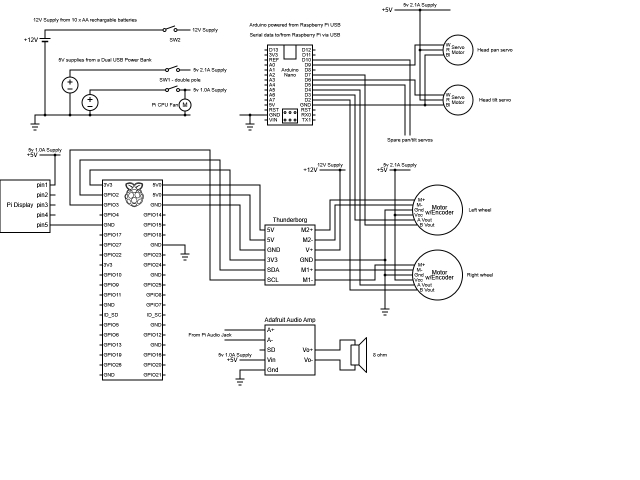
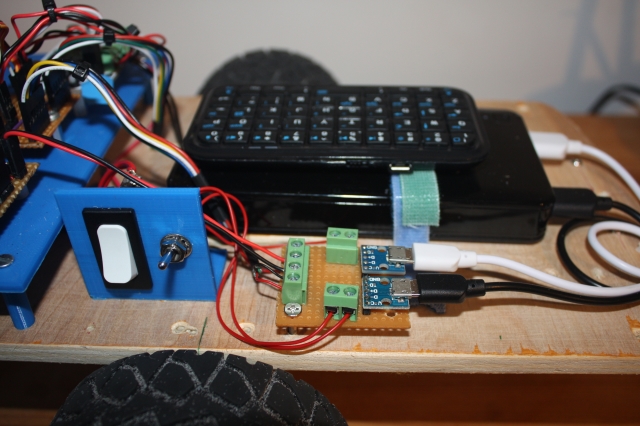
The circuit diagram shows that the Thunderborg board and motors are powered by 10 AA batteries, supplying 5V to the Raspberry Pi via the Thunderborg. The Nano is powered by the Raspberry Pi. Additionally, a USB power pack provides two distinct 5V rails: a 2.1A output for RC servos and motor hall sensors, and a 1.0A output for the display, audio amplifier, and CPU fan.
For the motors, the power and A/B signals from the right-hand motor's hall sensor are swapped compared to the left-hand motor, standardizing motor control and sensor feedback directions.
EaseRobot is currently under construction.
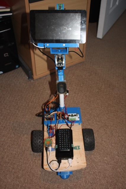
Two Micro USB breakout boards connect the USB power pack outputs.
EaseRobot's base includes a stowed mini Bluetooth keyboard, secured with Velcro, for easy Raspberry Pi interface during testing.
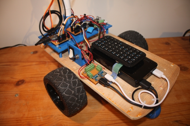
The rear platform houses the Arduino Nano, Thunderborg, and connection board.
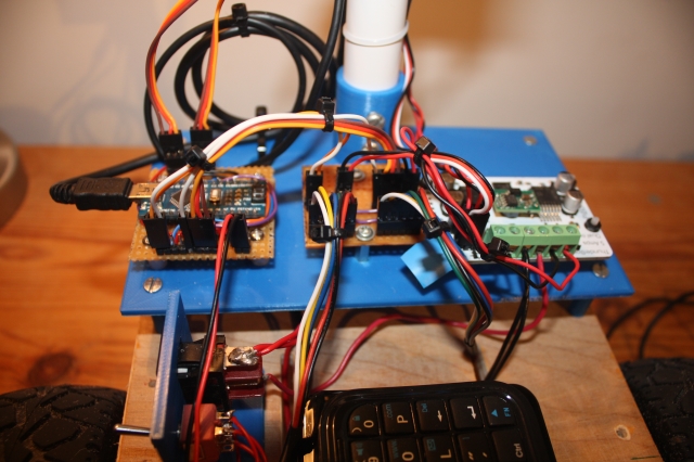
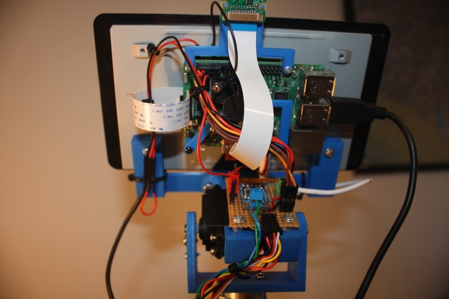
The display's rear view shows the Raspberry Pi, camera setup, and Vero board with the audio amplifier, also serving as an I2C junction for connections to the Thunderborg.
As a prototype, EaseRobot is subject to design revisions. Future plans include replacing the flexible plastic pipe used for the head with a more rigid material, potentially wood or a sturdy dowel. The rectangular robot base, initially designed for four wheels, may be reconfigured into a round design to accommodate its current two-wheel setup. Additionally, future upgrades aim to consolidate power sources into a single rechargeable battery, allowing autonomous recharging at a docking station. However, immediate focus remains on achieving full autonomy.
Summary
This section marks the completion of Design Goal 3, achieving locomotion control through a remote keyboard and/or joystick. Additionally, comprehensive circuit diagrams and a bill of materials have been compiled for the current build.
Next steps include integrating a laser range finder to fulfill Design Goal 4, enhancing EaseRobot's capabilities. Furthermore, an IMU will be incorporated to refine odometry performance.