EaseRobot - A Cutting-Edge Autonomous Robot
First installment in a series on a ROS-based Smart Home Bot
Introduction
The EaseRobot project is an innovative DIY robotics endeavor aimed at designing and building a sophisticated autonomous house-bot. This article marks the beginning of a series that will delve into the project's details. In this initial part, we'll introduce the concept, select a suitable single-board computer, install ROS (Robot Operating System), and develop the initial control software.
Background
In the late 1970s and early 1980s, I was inspired by two influential books: "How to build your own self-programming robot" by David L. Heiserman and "How to build a computer-controlled robot" by Tod Loofbourrow. The original plan was to design a custom processor board based on a Z80 processor and then build a robot around it. Unfortunately, the project never took off. Fast-forward to today, with the advent of compact boards like the Raspberry Pi and Arduino, creating a home robot has become significantly more accessible, although our expectations of its capabilities have increased dramatically.
As a nod to one of these books, our robot is named EaseRobot.
Unlike in the early 80s, we're fortunate to have a wide range of options available. EaseRobot will be built around a Raspberry Pi 3, Model B with 1GB of RAM, making it easier to focus on the robot's development rather than building a processor board from scratch.
Harnessing the Power of ROS and Raspberry Pi
I'll delve into how I've leveraged ROS in the EaseRobot project, highlighting how I've utilized various ROS tools to test and refine my code. While this isn't a comprehensive ROS tutorial, I'll provide essential ROS terms and concepts to facilitate a smooth read. For in-depth tutorials, I recommend exploring the ROS Wiki.
To begin with, here are some key ROS concepts:
- ROS is a distributed system, enabling robot code to run on multiple machines that communicate over a network.
- A node is a single-purpose executable that performs a specific task.
- Nodes are organized into packages, which are collections of folders and files.
- Nodes can be written in multiple languages, including C++ and Python, which we'll use in this project.
- Nodes communicate with each other using Topics, which are one-way streams of data.
- Topics are instances of Messages, which are data structures that can be standard or user-defined.
- Nodes can also communicate using Services, a server/client blocking protocol, and Actions, a non-blocking goal-oriented task protocol.
- The master node, roscore, is the central hub that all other nodes register with, ensuring seamless communication.
- ROS utilizes a catkin build system and provides various tools for examining and simulating the system.
- Individual nodes can be run using the rosrun command or the launch tool, which enables starting multiple nodes from a single command terminal.
- ROS includes a parameter server, allowing nodes to store and retrieve parameters during runtime.
With the decision to use a Raspberry Pi 3 as the main processor and ROS, the first step is to install ROS on the Pi. To simplify the process, I'll use an Ubuntu image for the Raspberry Pi that includes ROS, available for free from the Ubiquity Robotics website. This image features the Kinetic version of ROS and includes useful ROS packages, such as the raspicam_node for accessing the Raspberry Pi camera.
Other Raspberry Pi peripherals I plan to use in the EaseRobot project include:
- 7" Touchscreen Display
- Camera Module V2
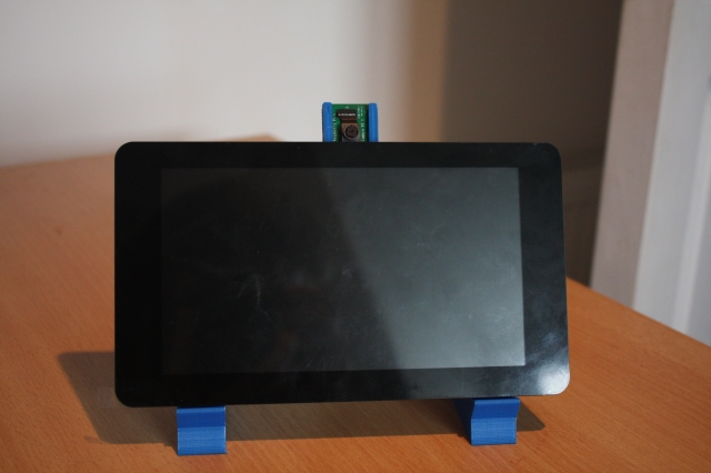
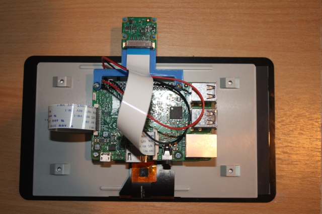
The display will be used to convey status information, web content, and an animated robot face to the user. The camera will serve as the robot's eyes, initially used for facial recognition.
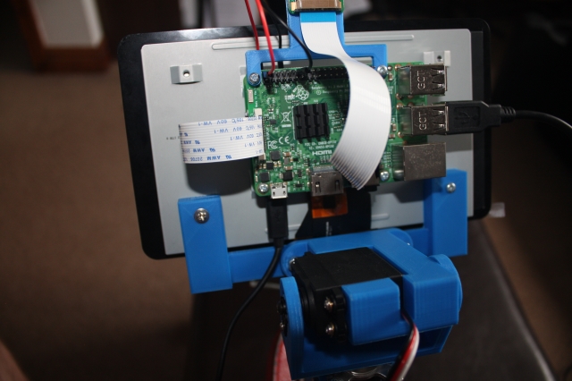
The following images show the 7" display with the Raspberry Pi and camera mounted on the rear of the screen. The camera is mounted using a 3D printed bracket, with the stl file available in the 3D print zip file included with this article.
As ROS can run across a distributed network, I've also installed ROS on an Ubuntu desktop. This desktop PC will be used to develop nodes for the system, run ROS tools to test the code, and simulate the robot's behavior.
Robotic Missions
To define the requirements for the EaseRobot project, I'll outline some "missions" that I'd like EaseRobot to perform. Inspired by the article "Let's build a robot!", one of the tasks I'd like EaseRobot to accomplish is:
Take a message to... - Since EaseRobot will have the ability to recognize family members, how about the ability to make it the'message taker and reminder'? I could say 'EaseRobot, remind (PersonName) to pick me up from the station at 6pm'. Then, even if that household member had their phone turned off or were listening to loud music, EaseRobot could navigate through the house, find the person, and deliver the message.
This sounds like a great starting point and will be our first mission. I'll modify it slightly, though. What if you could access EaseRobot using a web browser to control and set missions?
Let's break down the "Take a message to..." mission into several smaller design goals that can be worked on and completed individually. The design goals for this mission will be:
-
Design Goal 1: To be able to look around using the camera, search for faces, attempt to identify any people seen, and display a message for any identified.
-
Design Goal 2: Facial expressions and speech synthesis. EaseRobot will need to be able to deliver the message.
-
Design Goal 3: Locomotion controlled by a remote keyboard and/or joystick.
-
Design Goal 4: Addition of a laser ranger finder or similar ranging sensor used to aid navigation.
-
Design Goal 5: Autonomous locomotion.
-
Design Goal 6: Task assignment and completion notification.
That's quite a list of things to accomplish for what seems like a simple mission for a robot.
Mission 1, Design Goal 1
To accomplish this design goal, we will need to:
- Control the head/camera using RC servos for pan/tilt movement.
- Access images from the Raspberry Pi Camera.
- Detect and recognize faces.
- Control the order of these actions.
For the remainder of this first article, I'll concentrate on the pan/tilt control of the head/camera.
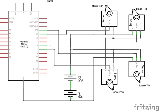
To control the head/camera, we need a pan and tilt device which will require two RC servos. I'm also going to include a second pan/tilt device for future expansion. We therefore require four PWM outputs to control the servos. The Raspberry Pi only has one hardware PWM, and although we could make use of software PWMs, I'm going to avoid that overhead by passing control of the servos off to a second board.
We could use a purpose-built board like the one available from PiBorg, the UltraBorg. Using this board, you can connect up to four servos and four HC-SR04 ultrasonic devices to the Raspberry Pi using an I2C bus. However, since I have a number of Arduino Nano's available from a previous project, I'm going to make use of one of those.
This is also going to be our first of many examples in taking advantage of work already carried out by the ROS community, allowing us to concentrate on the robot application. To attach to the ROS-like node which will be running on the Arduino, we are going to use a package that includes a node for communicating with the Arduino over the serial port and an Arduino library for use in the Arduino sketch. This package documentation is available on the ROS Wiki website rosserial_arduino.
To utilize this package, we'll need to install it on the ROS target and integrate the library into the Arduino IDE environment. Additionally, we'll need to rebuild the Arduino library if we define custom ROS messages (which we will). The rosserial Arduino tutorials provide a comprehensive guide on how to accomplish this and more.
To control the position of each servo comprising the pan/tilt devices, we'll develop a ROS package with a node that takes pan/tilt demand messages and converts them into individual position messages sent to the Arduino. The first message will specify which joints to move and their required positions. The second message, sent to the Arduino, will contain an index value indicating which of the four servos to move and the angle to which it should be moved. By breaking down this functionality, the Arduino sketch only needs to understand servo control, making it reusable for other servo applications. Note that in Arduino programming, the code running on the Arduino is referred to as a sketch, which I'll continue to use throughout this tutorial.
For the initial message, which specifies the joint positions, we'll utilize the ROS predefined message sensor_msgs/JointState. You can find the documentation for this message type here. As per ROS standards, the position units are radians, so our node will need to convert the position to degrees for the Arduino. The message also includes several fields that we won't be using. Although using this message type might seem excessive, adhering to ROS standards and leveraging existing message types will enable us to tap into valuable ROS tools later in the project.
The second message, which identifies the servo to move and the angle in degrees, will be a custom message to avoid unnecessary overhead in the Arduino sketch.
We could include the definition of our custom messages in the pan-tilt package, but to promote reuse, we'll create a separate package for the message definitions.
To complete the pan-tilt functionality, we'll develop two ROS packages and a ROS-style Arduino sketch.
We'll call the first package servo_msgs, which will define our custom message. Upon building, it will generate.h files for use by C++ code and automatically create Python scripts. We'll also recompile the Arduino library to produce.h files that will be used by our sketch.
The files comprising this first package are available in the servo_msgs folder. The root of this folder contains a readme file documenting the package, along with two files that are required in every ROS package: CmakeList.txt and package.xml. You can find information about these files in the tutorial on creating ROS packages.
The msg folder within the package contains the definition file for our message, servo_array.msg:
# index references the servo that the angle is for, e.g. 0, 1, 2 or 3
# angle is the angle to set the servo to
uint8 index
uint16 angle
Imagine this as a structured data format, similar to C. This message will be transmitted as a ROS topic to the Arduino, containing two essential elements: the index, which specifies the servo to be moved, and the angle, which defines the degree to which the servo should be rotated.
This concludes our first straightforward ROS package. Our second package is the pan_tilt package, located in the pan_tilt folder, which comprises executable code that will form the pan_tilt_node.
The root folder of this package includes a documentation file, as well as the CmakeList.txt and package.xml files. This package features several subfolders, which I'll briefly outline. The config folder contains the config.yaml file, which will be utilized by the launch file (discussed below) to set specific parameters in the parameter server. This enables us to configure the system without requiring code recompilation.
# In Rodney index0 is for the head and index 1 is spare
servo:
  index0:
    pan:
      servo: 0
      joint_name: 'head_pan'
    tilt:
      servo: 1
      flip_rotation: true
      max: 0.349066
      min: -1.39626
      joint_name: 'head_tilt'
  index1:
    pan:
      servo: 2
    tilt:
      servo: 3
In this configuration file, index0 specifies parameters for the head pan and tilt device, while index1 corresponds to the second pan and tilt device. The parameters are defined as follows:
- servo: identifies the servo responsible for the joint
- joint_name: specifies the name of the joint in the joint_state message
- flip_rotation: (explained below)
- max and min: defined in radians, these values restrict the joint's travel range
According to ROS convention, joints follow the right-hand rule, increasing their value in an anticlockwise direction around a positive axis. However, in Rodney's construction, the head tilt servo is mounted to follow the left-hand rule. By setting flip_rotation to true, our system can adhere to the convention while ensuring the pan_tilt_node passes correct values to the Arduino for the servo's orientation.
The cfg folder contains the pan_tilt.cfg file, which is used by the dynamic reconfiguration server to adjust servo trim on the fly. As seen, this file is a Python script.
#!/usr/bin/env python
PACKAGE = "pan_tilt"

from dynamic_reconfigure.parameter_generator_catkin import *

gen = ParameterGenerator()

gen.add("index0_pan_trim", int_t, 0, "Index 0 - Pan Trim", 0, -45, 45)
gen.add("index0_tilt_trim", int_t, 0, "Index 0 - Tilt Trim", 0, -45, 45)
gen.add("index1_pan_trim", int_t, 0, "Index 1 - Pan Trim", 0, -45, 45)
gen.add("index1_tilt_trim", int_t, 0, "Index 1 - Tilt Trim", 0, -45, 45)

exit(gen.generate(PACKAGE, "pan_tilt_node", "PanTilt"))
For a comprehensive understanding of the dynamic reconfiguration server, refer to the ROS Wiki section on dynamic reconfiguration. In our file, we add four parameters, one for each servo, with default values set to zero and minimum/maximum values set to -45 and 45, respectively.
The launch folder contains launch files that enable us to load configuration files and start all nodes that comprise a system. Our folder includes a pan_tilt_test.launch file for testing the pan/tilt part of the Rodney system. This is an XML-formatted file.
<?xml version="1.0"?>
<launch>
<rosparam command="load" file="$(find pan_tilt)/config/config.yaml" />
<node pkg="pan_tilt" type="pan_tilt_node" name="pan_tilt_node" output="screen" />
<node pkg="rosserial_python" type="serial_node.py" name="serial_node"
output="screen" args="/dev/ttyUSB0" />
</launch>
For a complete understanding of launch files, refer to the ROS Wiki section on launch files. Our launch file first loads the config file.
<rosparam command="load" file="$(find pan_tilt)/config/config.yaml" />
The next tag executes our pan_tilt_node, directing logging messages to the terminal.
<node pkg="pan_tilt" type="pan_tilt_node" name="pan_tilt_node" output="screen" />
The final tag runs the rosserial node, which communicates with the Arduino, selecting the serial port connected to the Arduino.
<node pkg="rosserial_python" type="serial_node.py" name="serial_node"
output="screen" args="/dev/ttyUSB0" />
The remaining folders, include and src, contain the C++ code for the package. Our package has one C++ class, PanTiltNode, and a main routine within the pan_tilt_node.cpp file.
The main routine initializes our node, creates an instance of our class, passes a callback function to the dynamic reconfiguration server, and hands control to ROS spin, which handles incoming and outgoing topics.
int main(int argc, char **argv)
{
ros::init(argc, argv, "pan_tilt_node");

PanTiltNode *pan_tiltnode = new PanTiltNode();

dynamic_reconfigure::Server<pan_tilt::PanTiltConfig> server;
dynamic_reconfigure::Server<pan_tilt::PanTiltConfig>::CallbackType f;

f = boost::bind(&PanTiltNode::reconfCallback, pan_tiltnode, _1, _2);
server.setCallback(f);

std::string node_name = ros::this_node::getName();
ROS_INFO("%s started", node_name.c_str());
ros::spin();
return 0;

}
The constructor for our class loads parameters from the parameter server setup by our configuration file.
// Constructor
PanTiltNode::PanTiltNode()
{
double max_radians;
double min_radians;
int temp;

/* Get any parameters from server which will not change after startup.
 * Defaults used if parameter is not in the parameter server
 */

// Which servo is used for what
n_.param("/servo/index0/pan/servo",  pan_servo_[0],  0);
n_.param("/servo/index0/tilt/servo", tilt_servo_[0], 1);
n_.param("/servo/index1/pan/servo",  pan_servo_[1],  2);
n_.param("/servo/index1/tilt/servo", tilt_servo_[1], 3);

// Check for any servos mounted the opposite rotation of the right-hand rule
n_.param("/servo/index0/pan/flip_rotation", pan_flip_rotation_[0], false);
n_.param("/servo/index0/tilt/flip_rotation", tilt_flip_rotation_[0], false);
n_.param("/servo/index1/pan/flip_rotation", pan_flip_rotation_[1], false);
n_.param("/servo/index1/tilt/flip_rotation", tilt_flip_rotation_[1], false);

/* Maximum and Minimum ranges. Values stored on parameter server in
 * radians and RH rule as per ROS standard. These need converting
 * to degrees and may need flipping.
 */
n_.param("/servo/index0/pan/max", max_radians, M_PI/2.0);
n_.param("/servo/index0/pan/min", min_radians, -(M_PI/2.0));
pan_max_[0] = (int)signedRadianToServoDegrees(max_radians, pan_flip_rotation_[0]);
pan_min_[0] = (int)signedRadianToServoDegrees(min_radians, pan_flip_rotation_[0]);
if(true == pan_flip_rotation_[0])
{
    temp = pan_max_[0];
    pan_max_[0] = pan_min_[0];
    pan_min_[0] = temp;
}

//... (rest of the code)

// Joint names
n_.param<std::string>("/servo/index0/pan/joint_name",
                       pan_joint_names_[0], "reserved_pan0");
n_.param<std::string>("/servo/index0/tilt/joint_name",
                       tilt_joint_names_[0], "reserved_tilt0");
n_.param<std::string>("/servo/index1/pan/joint_name",
                       pan_joint_names_[1], "reserved_pan1");
n_.param<std::string>("/servo/index1/tilt/joint_name",
                       tilt_joint_names_[1], "reserved_tilt1");

first_index0_msg_received_ = false;
first_index1_msg_received_ = false;

// Published topic is latched
servo_array_pub_ = n_.advertise<servo_msgs::servo_array>("/servo", 10, true);

// Subscribe to topic
joint_state_sub_ = n_.subscribe("/pan_tilt_node/joints",
                                 10, &PanTiltNode::panTiltCB, this);

}
The calls to param read the parameter from the server if it is available, otherwise, the default value is used.
n_.param("/servo/index0/pan_servo", pan_servo_[0], 0);
The last two lines of the constructor subscribe to the topic and advertise which topics our node will be publishing. The subscribe call is passed the callback function to be called when the topic arrives.
Our callback function is called panTiltCB.
// Callback to move the joints
void PanTiltNode::panTiltCB(const sensor_msgs::JointState& joint)
{
bool index0 = false;
bool index1 = false;

/* Search the list of joint names in the message. Although we expect pan/tilt
 * values for one device, a JointState message may contain data for one joint
 * or all four joints. The position (rotation) values are signed radians and
 * follow the right-hand rule. Values to be converted from signed radians to
 * degrees and for the servo orientation. Pan/tilt values are also stored in
 * case we change the trim.
 */
for (unsigned int i = 0; i < joint.name.size(); i++)
{
    // Is it one of the pan or tilt joints
    if(pan_joint_names_[0] == joint.name[i])
    {
        // Index 0 pan
        index0_pan_ = (int)signedRadianToServoDegrees
                      (joint.position[i], pan_flip_rotation_[0]);
        index0 = true;
    }
    else if(pan_joint_names_[1] == joint.name[i])
    {
        // Index 1 pan
        index1_pan_ = (int)signedRadianToServoDegrees
                      (joint.position[i], pan_flip_rotation_[1]);
        index1 = true;
    }
    else if(tilt_joint_names_[0] == joint.name[i])
    {
        // Index 0 tilt
        index0_tilt_ = (int)signedRadianToServoDegrees
                       (joint.position[i], tilt_flip_rotation_[0]);
        index0 = true;
    }
    else if (tilt_joint_names_[1] == joint.name[i])
    {
        // Index 1 tilt
        index1_tilt_ = (int)signedRadianToServoDegrees
                       (joint.position[i], tilt_flip_rotation_[1]);
        index1 = true;
    }
}

if(index0 == true)
{
    first_index0_msg_received_ = true;
    movePanTilt(index0_pan_, index0_tilt_, index0_pan_trim_, index0_tilt_trim_, 0);
}

if(index1 == true)
{
    first_index1_msg_received_ = true;
    movePanTilt(index1_pan_, index1_tilt_, index1_pan_trim_, index0_tilt_trim_, 1);
}

}
The callback function iterates through the names in the received message, searching for a known joint name. If a name is found, the associated position value is converted from the ROS standard and orientation to a value representing degrees on the servo using the signedRadianToServoDegrees helper function.
The callback then calls the function movePanTilt. This function adds in the trim offset for the relevant pan and tilt servos, checks if the range should be limited, and then publishes the two messages with the servo index and position. The two messages published are of the same type, one is for the relevant pan servo and the second is for the relevant tilt servo.
void PanTiltNode::movePanTilt(int pan_value, int tilt_value,
int pan_trim, int tilt_trim, int index)
{
int pan;
int tilt;
servo_msgs::servo_array servo;

pan = pan_trim + pan_value;
tilt = tilt_trim + tilt_value;

pan = checkMaxMin(pan, pan_max_[index], pan_min_[index]);
tilt = checkMaxMin(tilt, tilt_max_[index], tilt_min_[index]);

// Send message for pan position
servo.index = (unsigned int)pan_servo_[index];
servo.angle = (unsigned int)pan;
servo_array_pub_.publish(servo);

// Send message for tilt position
servo.index = (unsigned int)tilt_servo_[index];
servo.angle = (unsigned int)tilt;
servo_array_pub_.publish(servo);

}
There are two helper functions. The first is used to check for the max/min range.
int PanTiltNode::checkMaxMin(int current_value, int max, int min)
{
int value = current_value;

if (value > max)
{
    value = max;
}

if (value < min)
{
    value = min;
}

return (value);

}
The second helper function is used to convert the ROS standard units and orientation for rotation to those required by the servo.
// Converts a signed radian value to servo degrees. 0 radians is 90 degrees.
double PanTiltNode::signedRadianToServoDegrees(double rad, bool flip_rotation)
{
double retVal;

if(true == flip_rotation)
{
    retVal = ((-rad/(2.0*M_PI))*360.0)+90.0;
}
else
{
    retVal = ((rad/(2.0*M_PI))*360.0)+90.0;
}

return retVal;

}
The dynamic parameter server callback stores each of the trim parameters and then makes two calls to movePanTilt, one for each pan/tilt device, with the last position value and the latest trim values.
// This callback is for when the dynamic configuration parameters change
void PanTiltNode::reconfCallback(pan_tilt::PanTiltConfig &config, uint32_t level)
{
index0_pan_trim_ = config.index0_pan_trim;
index0_tilt_trim_ = config.index0_tilt_trim;
index1_pan_trim_ = config.index1_pan_trim;
index1_tilt_trim_ = config.index1_tilt_trim;

// We don't want to send a message following a call here unless we have received
// a position message. Otherwise the trim value will be taken for an actual position.
if(first_index0_msg_received_ == true)
{
    // Send new messages with new trim values
    movePanTilt(index0_pan_, index0_tilt_, index0_pan_trim_, index0_tilt_trim_, 0);
}

if(first_index1_msg_received_ == true)
{
    movePanTilt(index1_pan_, index1_tilt_, index1_pan_trim_, index1_tilt_trim_, 1);
}

}
The pan_tilt_node.h file contains the definitions for our PanTiltNode class.
Having completed the pan tilt package, the last coding task is to write the Arduino sketch. The sketch contains many of the elements used in the pan/tilt node. Our sketch is based on the servo tutorial for rosserial, but we need to modify it to access more than one servo and subscribe to our user-defined message.
Each Arduino sketch includes a setup and loop procedure. Our setup procedure initializes the node and subscribes to the servo topic. The remainder of the setup procedure attaches the pins 9, 6, 5, and 10 to the four instances of Servo.
The loop procedure simply calls spinOnce and then delays for 1ms. The call to spinOnce will handle the receipt of the topic.
Attached to the receipt of the servo topic is the callback function servo_cb. This function will be called each time the servo topic message is received, and it then simply adjusts the PWM output for the indexed servo.
/*

Based on the rosserial Servo Control Example
This version controls up to four RC Servos
The node subscribes to the servo topic and acts on a rodney_msgs::servo_array message.
This message contains two elements, index and angle. Index references the servos 0-3, and
angle is the angle to set the servo to 0-180.
D5 -> PWM servo indexed 2
D6 -> PWM servo indexed 1
D9 -> PWM servo indexed 0
D10 -> PWM servo indexed 3
*/
#if (ARDUINO >= 100)
#include <Arduino.h>
#else
#include <WProgram.h>
#endif

#include <Servo.h>
#include <ros.h>
#include <servo_msgs/servo_array.h>

/* Define the PWM pins that the servos are connected to */
#define SERVO_0 9
#define SERVO_1 6
#define SERVO_2 5
#define SERVO_3 10

ros::NodeHandle nh;

Servo servo0;
Servo servo1;
Servo servo2;
Servo servo3;

void servo_cb( const servo_msgs::servo_array& cmd_msg)
{
/* Which servo to drive */
switch(cmd_msg.index)
{
case 0:
nh.logdebug("Servo 0 ");
servo0.write(cmd_msg.angle); //set servo 0 angle, should be from 0-180
break;

case 1:
  nh.logdebug("Servo 1 ");
  servo1.write(cmd_msg.angle); //set servo 1 angle, should be from 0-180
  break;

case 2:
  nh.logdebug("Servo 2 ");
  servo2.write(cmd_msg.angle); //set servo 2 angle, should be from 0-180
  break;

case 3:
  nh.logdebug("Servo 3 ");
  servo3.write(cmd_msg.angle); //set servo 3 angle, should be from 0-180
  break;

default:
  nh.logdebug("No Servo");
  break;

}
}

ros::Subscriber<servo_msgs::servo_array> sub("servo", servo_cb);

void setup()
{
nh.initNode();
nh.subscribe(sub);

servo0.attach(SERVO_0); //attach it to the pin
servo1.attach(SERVO_1);
servo2.attach(SERVO_2);
servo3.attach(SERVO_3);

// Defaults
servo0.write(90);
servo1.write(120);
}

void loop(){
nh.spinOnce();
delay(1);
}
Implementing the Code
Before we can compile the sketch and program the Arduino, we need to build our ROS packages and recompile the ROS Arduino library. This step is crucial to make our user-defined message, servo_array, available in the Arduino IDE.
For this tutorial, I will be using a Linux workstation to run the Arduino IDE. I will build our packages on both the workstation and the Raspberry Pi. Although we are not utilizing any dedicated Raspberry Pi hardware at this stage, you can opt to run the nodes entirely on a workstation. I will run the nodes on the Raspberry Pi and run the test tools on the workstation, but you can choose to run the test tools on the Pi if you prefer. To distinguish between the Pi and the workstation in the instructions below, I have created a directory (workspace) called "ease_robot_ws" on the Pi and "test_ws" on the workstation.
Building the ROS Packages on the Workstation
ROS employs the catkin build system. To begin, we will create a catkin workspace and initialize the workspace. In a command terminal, enter the following commands:
$ mkdir -p ~/test_ws/src
$ cd ~/test_ws/
$ catkin_make
Next, copy the two package folders, pan_tilt and servo_msgs, into the ~/test_ws/src folder and build the code using the following commands:
$ cd ~/test_ws/
$ catkin_make
Verify that the build completes without any errors.
Building the Arduino ROS Library
I have the Arduino IDE installed on the workstation, which created an Arduino folder in my home directory containing a subdirectory "libraries". Note that when regenerating the library, you must delete the ros_lib folder using "rm -rf ros_lib" from within the "libraries" directory.
Use the following commands to build the ros_lib library:
$ source ~/test_ws/devel/setup.bash
$ cd ~/Arduino/libraries
$ rm -rf ros_lib
$ rosrun rosserial_arduino make_libraries.py.
Verify that the build completes without any errors and check that the servo_array.h file was created in the ~/Arduino/libraries/ros_lib/servo_msgs folder.
Building the servo Sketch and Programming the Arduino
Copy the ease_robot_control folder to the ~/Arduino/Projects folder. Start the Arduino IDE and open the ease_robot_control.ino file. From the Tools->Board menu, select the Arduino board you are using. In my case, it's the Nano. From the Tools->Processor menu, select the processor. In my case, it's the ATmega328P (Old Bootloader).
Build the sketch and check for any errors.
To program the Arduino, connect the device to a workstation USB port. In the IDE, from the Tools->Port menu, select the serial port that the Arduino is connected to. In my case, it's /dev/ttyUSB0.
Next, upload the sketch to the Arduino and verify that there are no errors reported.
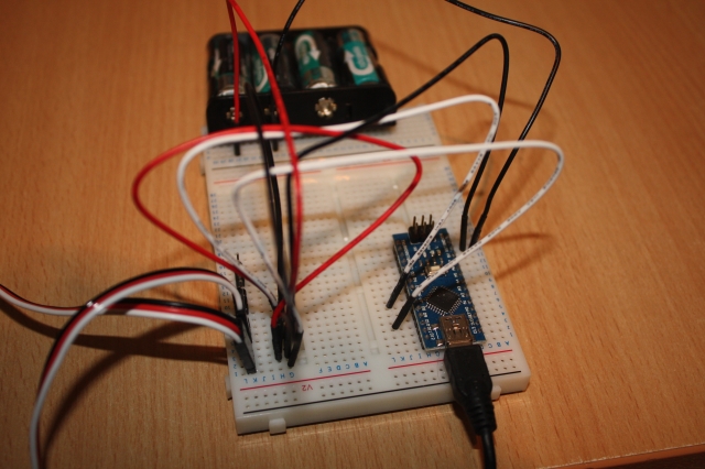
Arduino Circuit
When building EaseRobot, we need to consider power management. For now, I will power the Arduino using the USB port of the Raspberry Pi, while the servos will be powered from 4xAA rechargeable batteries. Below is a test circuit that illustrates the servo connections and power supply to the servos.
To test the software, I will build the circuit on a breadboard and connect only the servos for the head pan and tilt device.
Building the ROS Packages on the Raspberry Pi
Create a catkin workspace and initialize the workspace. In a command terminal, enter the following commands:
$ mkdir -p ~/ease_robot_ws/src
$ cd ~/ease_robot_ws/
$ catkin_make
Copy the two package folders, pan_tilt and servo_msgs, into the ~/ease_robot_ws/src folder and then build the code using the following commands:
$ cd ~/ease_robot_ws/
$ catkin_make
Verify that the build completes without any errors.
Tip
When running ROS code and tools on a workstation and the Raspberry Pi, you may encounter repetitive typing of commands in multiple terminals. To simplify this process, I have included the full commands to type below. Here are a few tips to save you from excessive typing:
On the Raspberry Pi, to avoid typing "source devel/setup.bash", I have added it to the.bashrc file.
$ cd ~/
$ nano.bashrc
Then add "source /home/ubuntu/ease_robot_ws/devel/setup.bash" to the end of the file, save, and exit.
When running test code and tools on the workstation, it needs to know where the ROS master is located. I have added the following to the.bashrc file for the workstation:
alias ease_robot='source ~/test_ws/devel/setup.bash;
export ROS_MASTER_URI=http://ubiquityrobot:11311'
By simply typing "ease_robot" at a terminal, the two commands are executed, saving you from repetitive typing.
Running the Code
Now that we have set up our code, we are ready to run it. With the Arduino connected to a USB port of the Raspberry Pi, use the launch file to start the nodes with the following commands. If no master node is running in the system, the launch command will also launch the master node, roscore.
$ cd ~/ease_robot_ws/
$ source devel/setup.bash
$ roslaunch pan_tilt pan_tilt_test.launch
In the terminal, you should see:
- A list of parameters now in the parameter server
- A list of the nodes, which should show pan_tilt_node and serial_node
- The address of the master
- The starting of the two nodes
- Log information from our code
We can now use some of the ROS tools to examine, interact, and test the system.
To test that the expected nodes are running and connected using the topics, open a command terminal on the workstation and type the following command:
$ cd ~/test_ws
$ source devel/setup.bash
If you launched the nodes on one device, for example, the Raspberry Pi, and want to run the tools on a second device, you need to tell the second device where to find the master. In the same terminal, type:
$ export ROS_MASTER_URI=http://ubiquityrobot:11311
Now, in the same terminal, start the graph tool:
$ rqt_graph
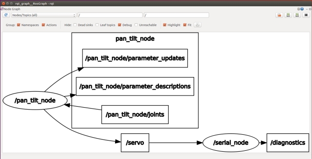
From the graph, you can see that the two nodes are running and are connected by the /servo topic. You can also see the topic /pan_tilt_node/joints.
We will now open a second terminal on the workstation and send a message to move the pan/tilt device using rostopic. In a new terminal, enter the following commands, don't forget to give the location of the master if running on a different device to that you launched the nodes on.
$ cd ~/test_ws
$ source devel/setup.bash
$ export ROS_MASTER_URI=http://ubiquityrobot:11311
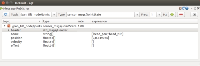
$ rostopic pub -1 /pan_tilt_node/joints sensor_msgs/JointState
'{header: {seq: 0, stamp: {secs: 0, nsecs: 0}, frame_id: ""},
name: [ "head_pan","tilt_pan"], position: [0,0.349066], velocity: [], effort: []}'
The last command will result in rostopic publishing one instance of the /pan_tilt_node/joints topic of message type sensor_msgs/JointState with the pan position 0 radians and the tilt position 0.349066 radians. If all worked fine, the servos will move to the position given. Note that at this stage of the project, the servos move straight to the new position. In the next article, we will add a node that will move the head in a more controlled manner.
It can be a bit long-winded to type the rostopic command. Alternatively, you can use rqt GUI. In the terminal, type:
$ rosrun rqt_gui rqt_gui
This will launch a window where you can select the Message Publisher, choose the message to publish, and the message fields' contents.
Due to the mechanical fittings of the pan/tilt device, it may be off-center by a number of degrees. You can trim the servos with the following procedure:
Set the position of both servos to the mid positions.
$ rostopic pub -1 /pan_tilt_node/joints sensor_msgs/JointState
'{header: {seq: 0, stamp: {secs: 0, nsecs: 0}, frame_id: ""},
name: [ "head_pan","tilt_pan"], position: [0,0], velocity: [], effort: []}'
In a new terminal, start rqt_reconfigure with the following commands, don't forget to give the location of the master if running on a different device.
$ cd ~/test_ws
$ source devel/setup.bash
$ export ROS_MASTER_URI=http://ubiquityrobot:11311
$ rosrun rqt_reconfigure rqt_reconfigure
This will bring up a user interface like the one shown below. Trim parameters can be dynamically adjusted via the interface.
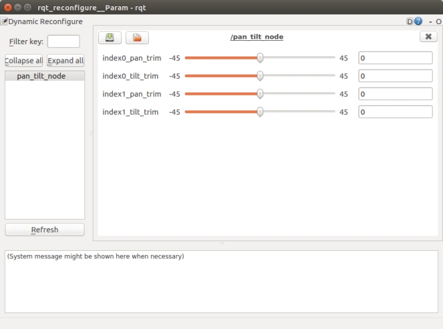
Once you are happy with the trim values, you can edit the pan_tilt.cfg to include the new trim values as the defaults. Then, the next time the nodes are started, these trim values will be used.
To terminate the nodes, simply hit Ctrl-c in the terminal.
Pan-Tilt Mechanism
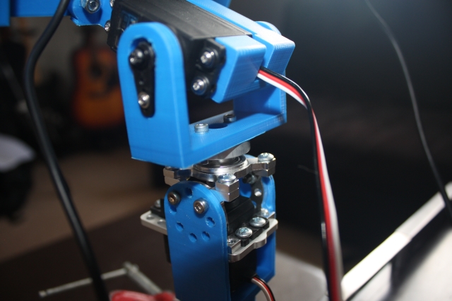
The EaseRobot's pan-tilt mechanism is comprised of two high-quality Futaba servos, specifically the S3003 and S3305 models. The S3305 servo, featuring metal gears, is employed in the pan position to ensure smooth and precise movement. Instead of purchasing a pre-made pan-tilt device, I opted to design and 3D print my own custom solution, with the STL files available for download. To mitigate the risk of the combined weight of the display and Raspberry Pi exerting excessive torque on the pan servo shaft, I incorporated a load-bearing servo block into the design. This innovative solution effectively enhances the mechanical load capacity of the servo, ensuring reliable operation. While this approach added to the overall cost of the robot, an alternative would be to mount the camera on a smaller pan-tilt device and fix the screen in place.
Key Takeaways
In this installment, we successfully integrated a ROS node from the broader ROS community into our EaseRobot system and developed our own custom ROS node. We have ROS running on the Raspberry Pi master board and have also leveraged the Arduino Nano to offload certain functionalities.
In the next installment, we will continue to work towards Design Goal 1 by integrating a Python-based face recognition library wrapped in a ROS node and developing a node to control the head movement.