EaseLock Hardware Tutorual
Create a custom smart lock device for your existing door that integrates an Atmega328 microcontroller, HC-05 Bluetooth module, and relay module, enabling remote operation from any paired Android device.
In this project, I will show you how to build a comprehensive prototype of smart lock step by step with minimal cost.
Introduction
Developing a product that goes beyond software requires mastering multiple technologies, which can be a daunting task. However, this diversity can also be the most fascinating aspect of the project.
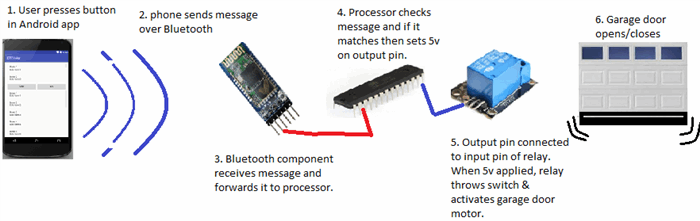
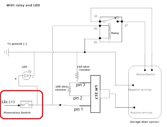
Below is a rough diagram that provides a comprehensive overview of the project. It illustrates all the necessary components and should give you a general understanding of how this system functions.
In general, this project allows to open your door via Bluetooth.
Components Summary
Essential Hardware Components for the Project:
- Bluetooth module (HC-05) - A wireless Bluetooth serial transceiver module for seamless connectivity
- Microcontroller: ATMega328P - A powerful AVR chip with Arduino UNO bootloader, available on Amazon
- Relay module - A 5V relay module compatible with official Arduino boards, ideal for switching applications
- Breadboard - A 3x solderless breadboard with 400 tie-points for easy circuit prototyping Assorted jumper wires for connections
- LED indicator for power status
- 220 Ohm resistor for LED circuit
- 22 pF disc capacitor for power filtering
- 5V power adapter/transformer with 850mA output, repurposed from an old Motorola Razr charger or available on Amazon"
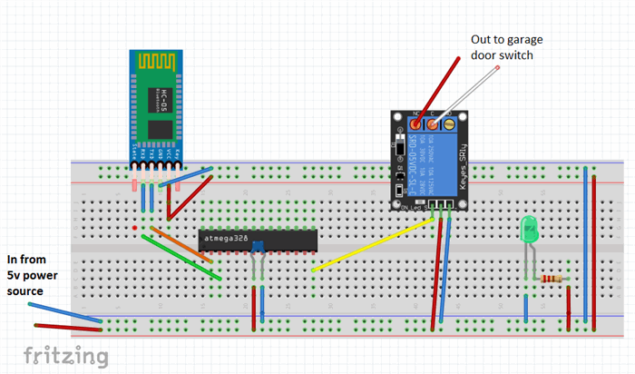
Fritzing Circuit
If you're familiar with the excellent app from fritzing.org, you know that it allows you to design and simulate your circuit. I've uploaded the completed board's schematic to: http://fritzing.org/projects/bluetooth-garage-door-opener
On the website, you can access the circuit diagram, customize it to suit your needs, and even test it.
As you can see from the final schematic, the electronics involved are surprisingly straightforward to build, and the required components are minimal.
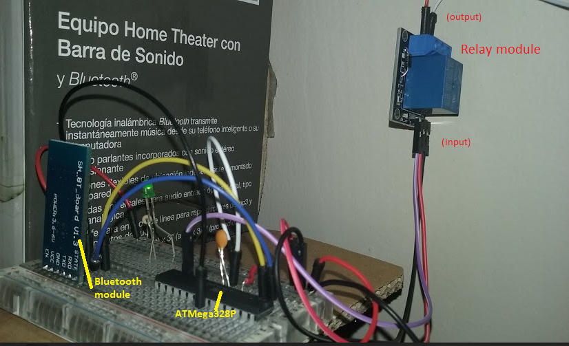
The Prototype
The prototype may still be in its rudimentary state on a breadboard, but it has proven to be a reliable performer, consistently opening many doors without a hitch every day.
Background
Upon moving into a new home, I was surprised to find an antiquated overhead door opener, but to my dismay, there were no wireless remotes included. Typically, a universal remote would suffice, but these old models required original LiftMaster remotes, which were scarce and pricey, with each one costing around $30USD. It's frustrating to be forced to purchase a separate remote at such a steep cost. It seems absurd, considering we all carry devices like phones and tablets that are more than capable of controlling a simple garage door, making the need for a dedicated remote seem redundant.
I Was Determined To Find A Way To Make It Work
As a seasoned software developer since 1995, I was determined to find a more efficient way to control my garage door. Initially, the concept of creating a wireless garage door control seemed daunting, requiring expertise in radio frequency (RF) and related complexities. However, I simplified the problem by focusing on the core requirement: remotely activating a switch.
At its core, a garage door opener is essentially a wall-mounted switch that controls the motor installed on the ceiling. When I press the switch, the motor is activated. Therefore, the fundamental challenge is to either replace the switch or find a way to activate it remotely, while ensuring that the existing wall switch continues to function as usual.
Identifying the Root Cause
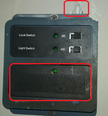
I began by examining the switch on my garage wall, which, I must admit, is quite outdated and aesthetically unpleasing. Upon closer inspection, I identified the incoming wires from the garage door motor at the top and the momentary switch at the bottom, which is pressed by the user to open or close the garage door.
A Crucial Hint: Garage Switch Safety
A crucial observation! I took note of the wire gauge, which, as a rough guideline, can indicate the voltage and current it carries. Please keep in mind that this is not professional electrical advice, and I strongly advise against attempting anything that makes you uncertain. Safety first!
As many of us familiar with garage door openers know, there are usually two thin wires connecting the switch to the motor on the ceiling. This suggests that they likely carry relatively low voltage and current. A quick internet search for "momentary switch garage door" reveals that these wires typically carry around 12 volts.
I stumbled upon a schematic that supports this, specifically a DIY guide on integrating a 3V garage door opener remote to a vehicle, found on the Toyota FJ Cruiser Forum.
First Step Is To Add Two Wires
My first step was to add two wires to extend the circuit to my new remotely controlled switch. I began by removing the switch from the wall and examining the wiring behind it.
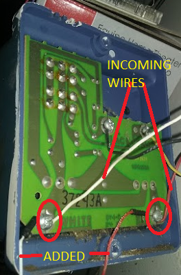
As shown, I can see the incoming wires from the garage door motor, and I added two new wires to the same screws by loosening them, curling the wires around them, and then tightening the screws back down.
After completing the addition and reassembling the panel, it looked like this:
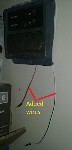
By touching the two wires together, I could activate the garage door motor (GDM), and conversely, if the GDM was already active, touching the wires together would deactivate it.
This step may seem straightforward, but it was a crucial milestone, as it demonstrated that if I could remotely control the connection of these two wires (completing the circuit), I would achieve my goal. What I needed now was an electronically activated switch to facilitate this remote control.
Electronically Activated Switch
Deep within my mind, a faint memory resurfaced - a valuable piece of information I had read in the exceptional book "Code: The Hidden Language of Computer Hardware and Software" by the renowned programming author, Charles Petzold.
Electronic Relay
Petzold also reveals that relays essentially function as switches that are operated by electromagnetic forces, which is exactly what I've been looking for.
How Do Relays Work?
The fundamental principle of a basic relay operates as follows: when a voltage is applied to the primary circuit, it energizes an electromagnet, which in turn attracts a metal armature, switching it from its normally open state to a closed state, thereby establishing a connection in the secondary circuit and allowing electrical current to flow, ultimately activating the device, such as the GDM.
Electromagnetic Coil: Wrapping Around an Iron Core
I'd like to break down the concept of relays in simple terms, so bear with me, electronics experts!
In essence, an electromagnet can be created by wrapping copper wire around a piece of iron, forming a coil. When electricity flows through the wire, a magnetic field is generated. This principle is the foundation of relay creation.
A basic relay consists of a coil and a metal piece that rests in one position and moves to the closed position when voltage is applied to the coil, causing the magnetic field to shift the metal switch.
Here's a simple circuit diagram of a relay, similar to the one I'm referring to:

Note that SPST stands for single-pole single-throw, meaning there's a single switch that switches in one direction.
Relay Basics: Keeping it Simple
You're right, creating a functional relay circuit involves more than just the relay itself. Even with modular relay units, additional components like diodes are necessary to ensure proper operation.
To simplify the process, I opted for a complete pre-made relay circuit module. These modules include all the necessary diodes and components to ensure reliable switching. They also provide easy connections for the primary and secondary circuits, making it a convenient and hassle-free solution.
Using a pre-made relay circuit module saved me time and effort, allowing me to focus on the overall project rather than delving into the intricacies of relay circuit design.
Relay Circuit Module: Affordable and User-Friendly
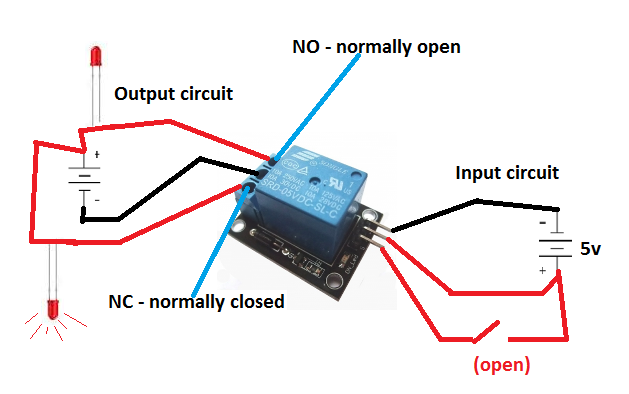
The relay circuit module I used in this project resembles the following:
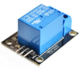
This module is not only inexpensive but also incredibly easy to use, making it perfect for my project.
I purchased the relay module through Amazon, and you can also get yours from there if you're interested: Tolako 5v Relay Module for Arduino.
The large blue box at the center of the circuit board is the actual relay, which consists of a coil that generates a magnetic field, moving the switch. Note that this device is marketed as being "for Arduino" because most people programming AVR ATMega chips use Arduino boards. However, it works perfectly fine with our setup, and the manufacturer could have just as easily marketed it as compatible with AVR chips. The "Arduino" label is likely due to its popularity and buzz.
Output Circuit
The first view displays the output circuit, consisting of three ports where our wires will be connected. Each port has a screw that allows for secure connection of the output wires without the need for soldering. This is the circuit that we will connect our garage door motor (GDM) wires to. If you refer back to the original picture where I added the two wires to my switch, you'll see that those two wires will be connected to two of these output ports. This is evident in the first picture of the completed project. This circuit will ultimately be activated when we want to trigger our GDM.
Input Circuit
In addition to the output circuit, we also need to provide an input circuit to use the relay module. The input circuit determines whether the garage door motor (GDM) should be activated or not. We'll discuss more about this input circuit as we progress. As shown in the second view of the relay module, the input circuit consists of three pins.
The Mystery of the Three Input Pins
The operational principle of a relay module is straightforward. To activate it, you need to connect a positive voltage source (ranging from 5 to 12 volts) to the positive terminal, and a ground wire to the negative terminal. Next, you'll need to connect another wire to a separate power source that supplies a similar voltage range. This power source is linked to the pin labeled IPP (which likely stands for Input Port) on the relay module. When a 5-volt signal is applied to this pin, the coil is energized, the electromagnet is activated, and the switch is turned on, thereby completing the circuit on the output side.
The Three Output Ports: NO, NC, and COM
The three output ports on the relay module are:
- NO (Normally Open): This port is connected to the relay's normally open contact. When the relay is de-energized, this port is disconnected from the COM port. When the relay is energized, this port connects to the COM port.
- NC (Normally Closed): This port is connected to the relay's normally closed contact. When the relay is de-energized, this port is connected to the COM port. When the relay is energized, this port disconnects from the COM port.
- COM (Common): This port is the common terminal that connects to either the NO or NC port, depending on the relay's state.
Having three output ports allows you to configure the relay to suit your specific application. You can use the NO port to connect a device that should be turned on when the relay is energized, or use the NC port to connect a device that should be turned off when the relay is energized. The COM port provides a convenient connection point for the load circuit.
The circuit looks like the following:
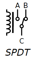
In the preceding diagram, we're looking at the schematic representation of the non-energized state of the circuit. As you can see, the B-C circuit corresponds to the normally closed (NC) state, while the A-C circuit represents the normally open (NO) state.
Now that we have the key component in place, let's integrate it into a simple circuit to demonstrate its functionality. We'll design the circuit so that when voltage is applied to the IPP, the switch will toggle, and an LED will illuminate on the output side.
I'll start by illustrating the simple circuit.
The Relay: A Bridge Between Three Circuits
Our relay module consists of three separate circuits, each with its own distinct function.
- First, there's the input circuit, which plays a crucial role in determining which output circuit is active.
- Then, there's the normally closed (NC) output circuit, which remains active when no voltage is applied to the IPP. As you can see in the next diagram, when the IPP is not powered, the LED on the NC output circuit is illuminated.
- Lastly, there's the normally open (NO) output circuit, which is designed to operate in tandem with the NC circuit.
If we were to activate the switch in the input circuit, the state of the output circuit would change. The switch would toggle, causing the normally closed (NC) circuit to open, which would extinguish the LED. Simultaneously, the normally open (NO) circuit would close, allowing the top LED in the diagram to illuminate.
Have We Devoted Too Much Attention To The Relay Module?
Perhaps, but consider the significance of this fundamental component. Mastering its operation unlocks a vast range of control possibilities, empowering you to tackle a multitude of future projects.
Moreover, this relay is the linchpin of our current project, as it provides the electronic switch we need to flip. By grasping this concept, you'll be able to harness the power to control a wide spectrum of electrical devices, limited only by your imagination.
What Triggers The Relay's Voltage Application Remains A Question.
I manually applied the 5V to the input pin using a wire.
Signal Activation
We need to find a way to send a signal to the relay, instructing it to activate and flip the switch, thereby starting the garage door motor (GDM).
One possible approach would be to create a wired solution, where pressing a button from a distance would apply 5V to the wire connected to the relay module's IPP, activating the magnetic coil and starting the GDM. However, this is not a practical solution for our situation, as it's essentially what we already have with our wall switch. Instead, we want to receive a wireless signal to activate the GDM.
Bluetooth, being a wireless technology, offers a promising solution. I've been following Adafruit Industries' videos and keeping up with their innovative DIY electronics and kits, and I believe I've seen some affordable Bluetooth components that could fit the bill.
The Bluetooth
In an effort to keep costs and complexity to a minimum, I began searching for a suitable Bluetooth module. My search led me to a remarkably simple, albeit poorly documented, module that appears to be an industry de facto standard, with multiple manufacturers producing their own versions.
HC-05 Bluetooth Module
I finally settled on a particular Bluetooth module, which I was able to purchase from Amazon for approximately $8.00USD. The specific model I chose is the HC-05 Wireless Bluetooth Serial Transceiver Module, available in both slave and master configurations. Below, you can see the front and back views of the module.
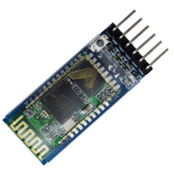
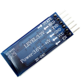
Device Pins: Gateways to Functionality
The back view of the module provides valuable insights into its operation. We can see that powering up the device requires a simple connection: providing 3.6v to 6v to the VCC pin and grounding the GND pin to complete the circuit.
Using the Bluetooth Module (Mostly) Straightforward
In essence, if we were to connect the module to a breadboard, add a power source within the 3.6v-6v range, and wire it up correctly, the module would begin broadcasting a Bluetooth signal, allowing other devices to connect.
The Key Question: Communicating with the Bluetooth Device
However, once the module is powered up, broadcasting, and a device has connected, the crucial question remains: how do we communicate with the Bluetooth device? How do we receive messages from the connected device and use them to activate our relay, ultimately starting the garage door motor (GDM)? We'll explore the answer to this question soon. For now, let's continue examining the Bluetooth module's pins and their functions. Before we do, though, it's essential to discuss the importance of voltage compatibility when selecting components.
Voltage Considerations
It's crucial to note the voltage ranges of our devices. The relay module operates within a range of 5v to 12v, while the Bluetooth module functions within a narrower range of 3.6v to 5v. This is significant, as we'll need to ensure that our power supply can accommodate both devices on the same circuit. Later, when we discuss the Atmel ATMega328 chip, we'll learn that it has an operating voltage range of 1.8v to 5.5v.
Now, let's refocus on the HC-05 Bluetooth module. It's time to connect it, pair it with a device, and explore its capabilities.
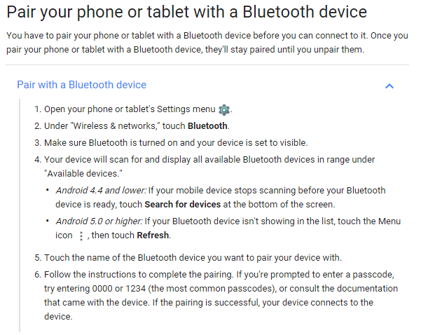
Bring Up Bluetooth Module And Start Pairing
The general steps on how to pair a device is shown as follows. The default password for the HC-05 module is 1234 and we will need to generate a dynamic one in the next tutorial.
Interacting with the Bluetooth Module
Now that we've successfully paired a device with the Bluetooth module, we need to understand how to communicate with it. How can we send and receive data from the module, and how can we confirm that we're successfully interacting with it?
The Bluetooth Module's Simple Functionality
The Bluetooth module's primary function is straightforward: it sends and receives data. The challenging part is working with the received data. Essentially, the module performs two key tasks:
It receives wireless data and transmits it to its serial transmit pin (Tx) as a series of voltages, similar to Morse code. When data is written to the Rx pin on the Bluetooth module, it converts that data into a wireless signal and transmits it. This means that if we can detect when voltages are present on the Tx pin, we can determine that a message is available to read. Conversely, if we want to send a message via the Bluetooth module, we need to write voltages to the Rx pin.
The Data Dilemma
The crux of the issue is that we can't access the data received by the Bluetooth module. Take a moment to consider this problem. How can we read the voltages on the Tx pin? One possible approach would be to directly connect the Tx pin to the relay's IPP (input port). However, this would result in every bit of data received by the Bluetooth module triggering the relay numerous times a second, causing the garage door motor (GDM) to activate and deactivate rapidly. This solution is clearly impractical.
The Need for Processing Power
What we really need is a component that can process the incoming data from the Bluetooth module. We require a way to write a program that can analyze the data and make decisions based on it. Since the Bluetooth module itself cannot be programmed to process data, we need another component to perform this task. This is where the ATMega328PU microprocessor comes in – the central processor of our project.
The Atmel ATMega Chips
As a product developer, I'm more concerned with getting our project done efficiently and cost-effectively. Let's focus on the ATMega chip from a practical perspective. What's driving the popularity of these chips?
The AVR chips, first introduced in 1996, were among the pioneers in the microcontroller market. They...
"..one of the first microcontroller families to use on-chip flash memory for program storage, as opposed to to one-time programmable ROM, EPROM, or EEPROM used by other microcontrollers at the time."
This innovative technology enabled the AVR chips to have programs easily flashed into their memory, a significant advantage over their predecessors.
Arduino Boards
The pioneering work of Massimo Banzi and his team paved the way for the creation of Arduino, an open-source hardware platform that revolutionized the world of embedded programming.
In 2005, the first Arduino boards were released, offering an affordable ($30-$40) and accessible way for hobbyists to dive into embedded programming. The team chose to base Arduino on Atmel chips due to their:
- Low cost
- Easy programming (flash memory)
- Simple programming (easy to write programs for)
- Built-in functionality (serial communication, etc.)
- Good performance
Prior to Arduino, hobbyists faced a significant barrier to entry, with investments of hundreds of dollars just to get started with programming a chip. Arduino and Atmel chips dramatically reduced this cost, making embedded programming more accessible to a wider audience.
The open-source nature of Arduino development boards further drove down prices, as anyone could build and sell them. This democratization of embedded programming enabled a new generation of makers and innovators to explore the world of microcontrollers.
The ATMega328: A Cost-Effective Solution
One of the key advantages of the ATMega328 is its affordability. I was able to purchase two of these chips for a mere $10.99USD on Amazon, complete with the Arduino UNO bootloader: Amazon.com.
Seamless Serial Communication
The ATMega328 also offers easy access to its functionality via its pins, including built-in serial communication capabilities. This is particularly useful for our project, as we can leverage the chip's Transmit (Tx) and Receive (Rx) pins for serial communication. For a detailed look at the chip's pins, refer to the diagram from Atmel's documentation.
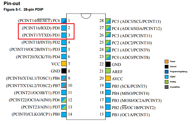
As indicated by the red box, the diagram above shows two serial communication pins labeled TXD and RXD.
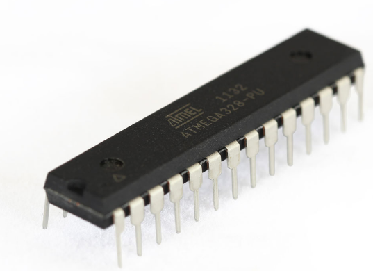
The 28-pin ATMega328P chip is depicted as follows:
Connecting Bluetooth is a breeze
As you'll soon see, these pins make it incredibly convenient to connect our chip to the Bluetooth module, enabling us to receive data from Bluetooth and transmit data back via Bluetooth. The process involves simply linking the Bluetooth's Tx to the chip's RXD and the Bluetooth's Rx to the chip's TXD.
Next, let's establish power connections for the ATMega chip and the Bluetooth module, and then create a C program to be flashed onto the chip, which will retrieve data from the Bluetooth device.
Configuring the Flash Programmer
To begin, we need to set up our board to enable flashing of our program to the chip - essentially, writing our program into the ATMega chip's flash memory.
Typically, we would be using an Arduino programming board at this stage. However, I prefer a more cost-effective approach, opting to work directly with the chip's core and program in pure C. Therefore, I'm recommending an alternative device.
I highly recommend purchasing the following flash programmer, which has proven to be very effective and affordable ($10.50USD):
Configuring the Flash Programmer
Obtain the Necessary Drivers
Begin by connecting the device to your USB port and installing the required drivers from:
Installing AVRDude
Next, download and install AVRDude, a free and open-source software that compiles your C programs using the GNU C compiler and flashes the program into your chip's memory.
You can obtain AVRDude from: /releases/avrdude
Download the latest release, extract the files, and then you'll be able to run AVRDude from the command line.
Overcoming Setup Obstacles
While I'm aware that setting up this programming environment can be challenging, I'll keep this article concise and won't delve into the details.
Valuable Resource for Setup
The book that helped me navigate the process and start programming Atmel chips is: AVR Programming: Learning to Write Software for Hardware by Elliot Williams, eBook - Amazon.com. You don't need to read the entire book, but the first two chapters will provide sufficient guidance to get you set up.
From this point on, I'll assume that you have your environment configured, connected, and are ready to flash a program to the chip.
Bluetooth Module Byte Reading Program Example in C
Here is a straightforward C program that reads incoming bytes from the Bluetooth module and subsequently determines the course of action based on the received data.
#include <avr/io.h>
#include <util/delay.h>
#include "pinDefines.h"
#include "USART.h"

int main(void) {
  char serialCharacter;
  DDRB |= 0b0000001;
  initUSART();

  while (1) {
    serialCharacter = receiveByte();
    transmitByte(serialCharacter);
    if (serialCharacter == 'y')
    {
        PORTB = 0b00000001;
    }
    if (serialCharacter == 'n')
    {
        PORTB = 0b00000000;
    }
    _delay_ms(100);
  }
  return 0;
}
This is just a simple example. In the next tutorial, I will explain how to develop the software stack step by step.