EaseCar
Revolutionizing the World of RC Cars
When it comes to hacking RC cars, we've seen it all - from Bluetooth connectivity to gesture control. But what if we told you that we're about to take it to the next level? Imagine a car that not only responds to your voice and gestures but also navigates through obstacles on its own, all while live-streaming events to YouTube.
You might be thinking, "So what's the big deal? We've seen similar projects before." But here's the twist - our car, dubbed EaseCar, combines multiple modalities into one seamless experience. It's not just about controlling a car with different inputs; it's about creating an immersive experience that solves real-world problems.
As a seasoned developer, I've had my fair share of DIY projects, but I wanted to push the boundaries of what's possible with IoT. I wanted to create something that would not only impress but also provide value to users. That's why I embarked on this ambitious project, which combines cutting-edge technologies like Intel Edison, computer vision, and machine learning to create a truly autonomous and interactive experience.
In this series of articles, we'll take you on a journey to build EaseCar from scratch. Whether you're a seasoned IoT developer or a C# enthusiast, you'll find something valuable in this project. So, buckle up and get ready to revolutionize the world of RC cars
EaseCar Design
As we've established in the last section, our goal is to create a multi-modality RC car that responds to various devices and commands. To achieve this, it's essential to understand the system architecture before we begin building.
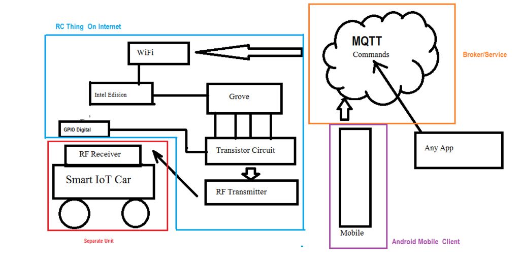
Let's take a closer look at the control block diagram of the car, as shown in the following figure.
Next, let's examine the hack concept.
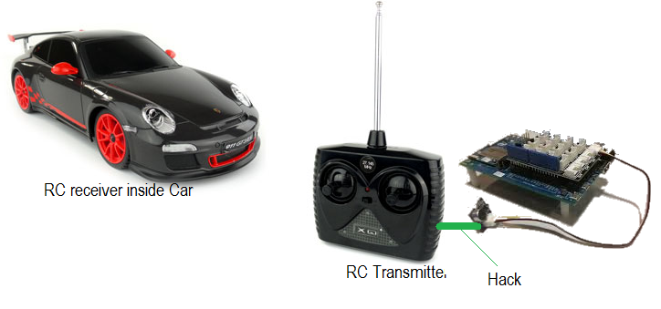
As we can see, a typical RC car operates at standard RF frequencies, with 27MHz being a popular choice for toy RC cars. The car has two isolated circuits: a transmitter at the remote and a receiver circuit in the car. The remote generates different pulses at the tuned frequency, which are received by the car's circuit and control a H-Bridge that drives the motors responsible for movement. Most commercial toy cars have two motors: one for left-right movement and another for forward-reverse movement. By controlling both motors simultaneously, we can achieve four possible movements: forward-left, forward-right, reverse-left, and reverse-right.
To transform this RC car into an IoT car, we need to hack either the transmitter, the remote control, or the actual car and connect the H-Bridge directly to our IoT embedded device circuit. However, hacking the transmitter is the most elegant solution, as it allows us to keep the car's internal circuitry intact.
I previously built a RC car hack to enable my son to drive the car using his mobile phone. However, kids often prefer a clean and mess-free experience. Therefore, hacking the transmitter is the best approach, as it allows us to replicate the functionality of the remote control programmatically.
We'll be using the Intel Edison with an Arduino-compatible Expansion Board as our IoT device. The archicture diagram provides a clear idea of what our EaseCar will look like.
The question is, how do we replicate the functionality of the four remote buttons? The answer lies in the first figure. We'll run an MQTT server on our IoT device, and different apps (mobile or PC) will publish commands to this MQTT channel. Depending on the commands, the board will programmatically control the switches.
The beauty of this approach is that we can build apps to support various modalities and simply hook them up to the MQTT channel subscribed by our Edison device. This flexibility allows us to integrate multiple control methods seamlessly.
Of course, we also need to integrate a camera with our car and stream live footage to YouTube. But first, we need to hack the car to get it working programmatically. We'll cover that in the next section.
Are you ready to dive in?
Let's Rock And Roll
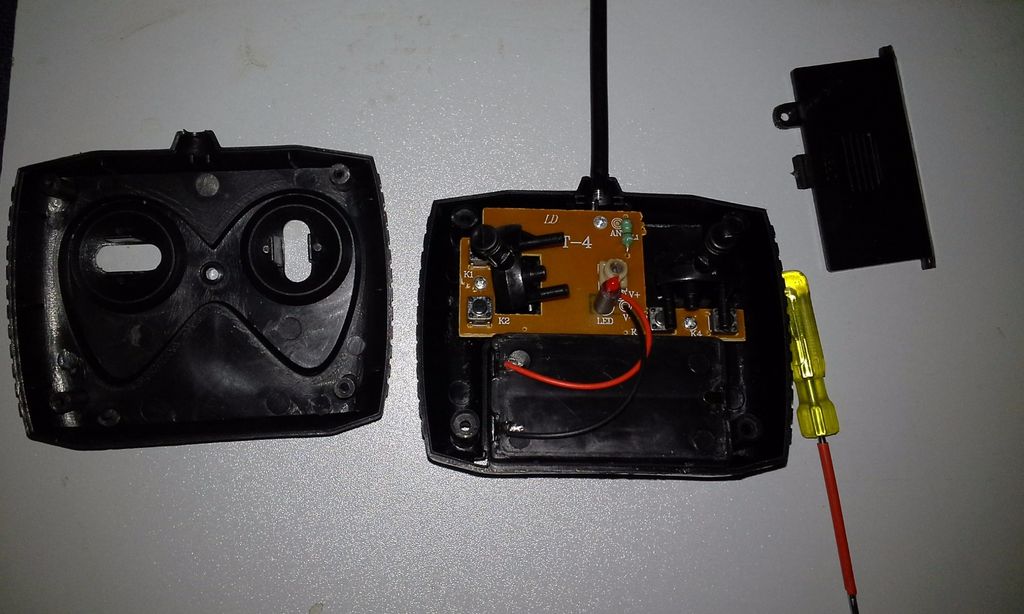
To begin, take a small screwdriver and open the remote control. You'll find the circuit board inside, with a pair of wires (one red and one black) connected to the battery box. These wires are your power lines. You'll also see the forward and reverse handles and left and right push buttons. Since we no longer need these control handles, simply unscrew and remove them from the circuit.
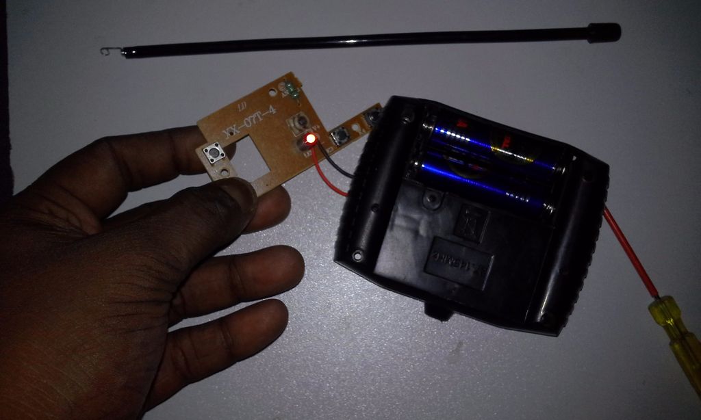
In this image, you can see the isolated circuit after it's been unscrewed from the remote body. Now, you can push the buttons and observe how the circuit is powered by the battery box.
Our first step is to cut these two wires from the battery box and power the circuit from our device.
To do this, you'll need a Grove connector cable. The cable has two ports at either end, one for connecting to the Grove shield and the other for connecting to Grove component modules like LEDs. Cut one of the ports, so that one port of the cable is connected to the shield, and the other end has four wires: Red, Black, Yellow, and White. Observe the labels on the ports of the Grove shield to understand that the Red wire is mapped to Vcc, Black to Ground, and Yellow to the pin corresponding to that port. To give power to the remote RC module, separate the Red and Black wires from the battery box and wire them with the Red and Black wires of the cable you just cut.
Once you've powered up your RC module with your Grove shield, ensure that the power is driving the remote correctly. Switch on your car, and press the buttons manually to see your car moving.
So, you've just connected your RC module with your Edison board. But in real terms, it's still controlled through its onboard push buttons. Right? So, our next task is to give the control of these push buttons to our Edison board.
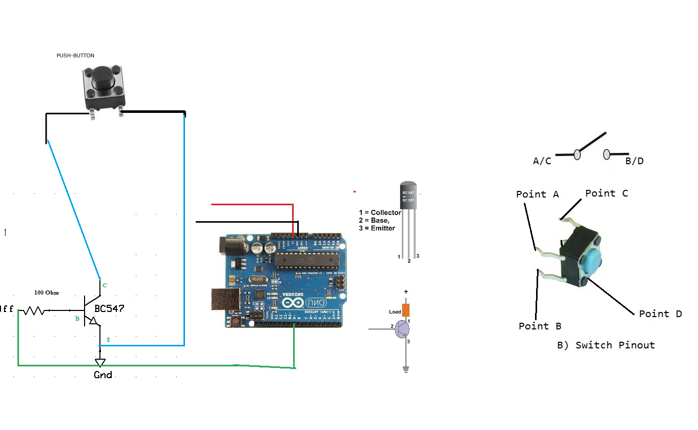
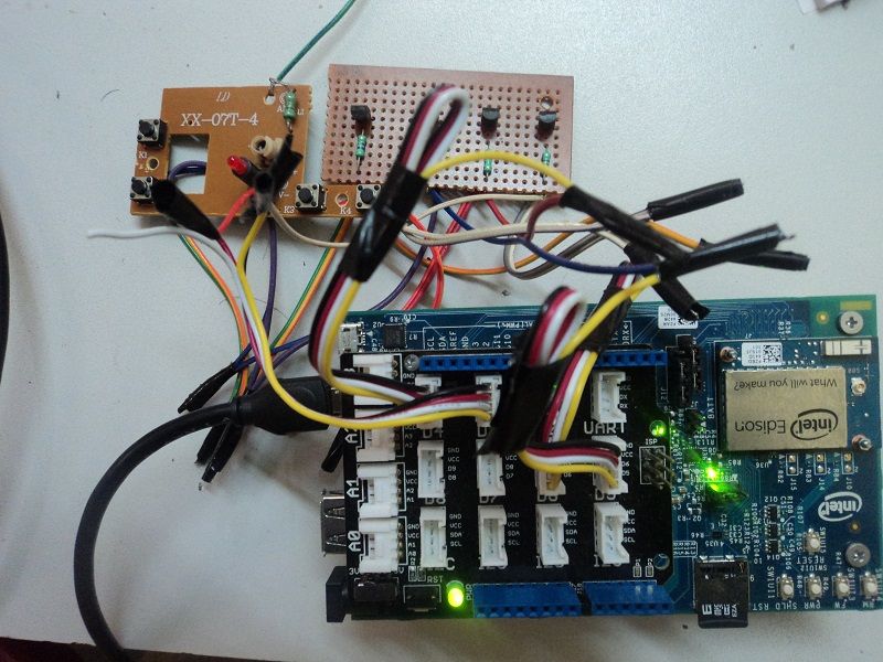
If we were to hack the remote for Arduino, it would look like this:
As Intel Edison is an Arduino-compatible board, the circuit remains similar. BC 548/547 is connected with a 100Ohm resistor with the Yellow wire of the Grove cable, Red with the remote's Red (or VCC), and the cable's Black with the remote's Black. That's it. You'll need four transistors and four resistors to bypass all the switches.
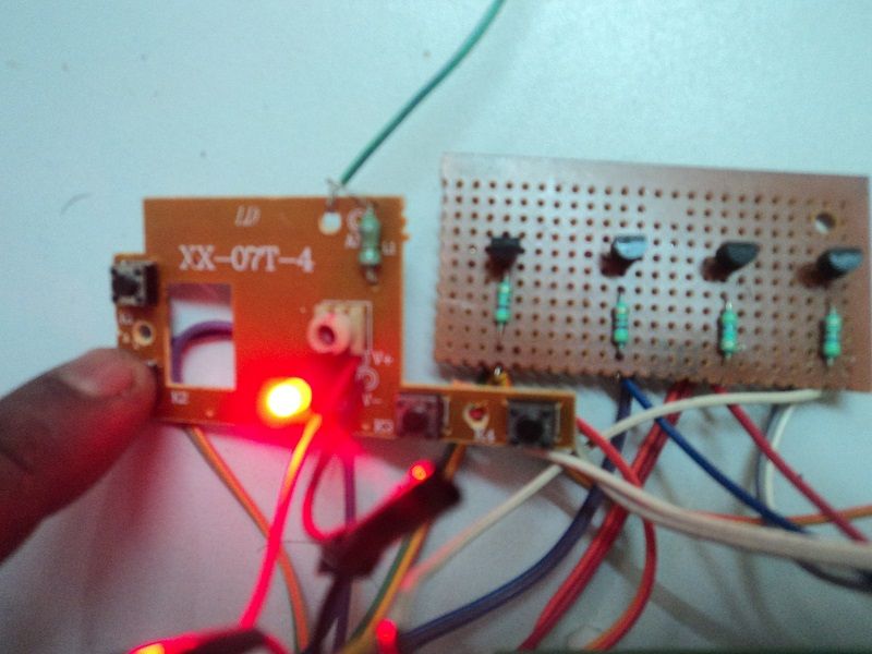
Once you've completed the circuit, simply connect the port-connected parts of the cable on the Grove shield (D5-Forward, D6-Reverse, D4-Right, D3-Left). The circuit is as shown below.
Coding for RC Car
In this chapter, we'll dive into the coding process for our EaseCar project. We'll create two apps: an IoT device app in Node.js to control our RC car, and a corresponding mobile app to interact with the car.
IoT Device App in Node.js for Controlling Our RC Car
To ensure a seamless user experience, we need to minimize latency in our RC car's response to commands. While MQTT messaging is an excellent way to bridge the gap between our client app and IoT app, it introduces latency that can be frustrating for users. To overcome this, we'll run a local MQTT broker on our Intel Edison board.
Fortunately, installing Mosquitto, an IoT MQTT message broker, on Edison is a breeze. Here's how:
Installing Mosquitto MQTT Broker in Edison
Open the Edison Shell and type the following command to download the Mosquitto bundle:
wget http://mosquitto.org/files/source/mosquitto-1.3.5.tar.gz
Untar the zip folder:
tar xzf mosquitto-1.3.5.tar.gz
Install Mosquitto:
cd mosquitto-1.3.5
make WITH_SRV=no
That's it! Your Intel Edison board will now run a Mosquitto MQTT broker on port 1883 at startup.
Testing the MQTT Broker
Open two PuTTY terminals and connect to your board through SSH. In one shell, subscribe to a message using the following command:
mosquitto_sub -h EDISON_IP -p 1883 -t CHANNEL_NAME
Replace EDISON_IP with your board's IP address and CHANNEL_NAME with the desired channel name (e.g., rupam/data).
In the other terminal, publish a message using the following command:
mosquitto_pub -h EDISON_IP -p 1883 -t CHANNEL_NAME -m "SOME_MESSAGE"
You should see the published message appear in the first shell where you subscribed.
Testing with Mobile
If you're an Android user and aspiring IoT developer, consider installing the MyMQTT app. In MyMQTT, subscribe to the CHANNEL_NAME for the broker EDISON_IP. If you're unsure about your Edison IP address, use the ifconfig command to find it.
Node.js Code
Our Node.js code revolves around subscribing to the rupam/data channel using the MQTT module. We'll then control pins D3, D4, D5, and D6 based on the received command.
An essential aspect to consider is that the RIGHT and LEFT commands only bear meaning when used in conjunction with FORWARD and REVERSE. Additionally, in either FORWARD or REVERSE mode, the car may have RIGHT, LEFT, or straight movement (no RIGHT or LEFT).
To address this, we've developed two extra commands: NO (when LEFT=0 and RIGHT=0) and STOP (when all switches are 0).
var mqtt = require('mqtt');
var client = mqtt.connect('mqtt://192.168.1.101'); // change to Edison's local IP address

var mraa = require('mraa');
var SPEED = 1;

// Remote Pins
var fPin = new mraa.Gpio(6);
var bPin = new mraa.Gpio(5);
var rPin = new mraa.Gpio(3);
var lPin = new mraa.Gpio(4);

// Set up Pins
fPin.dir(mraa.DIR_OUT);
bPin.dir(mraa.DIR_OUT);
rPin.dir(mraa.DIR_OUT);
lPin.dir(mraa.DIR_OUT);

// Initialize
fPin.write(0);
bPin.write(0);
rPin.write(0);
lPin.write(0);

// Subscribe to MQTT topic
client.subscribe('rupam/data/#');

// Handle incoming MQTT messages
client.handleMessage = function(packet, cb) {
  var payload = packet.payload.toString();

  if (payload === 'FORWARD') {
    bPin.write(0);
    fPin.write(SPEED);
  }

  if (payload === 'REVERSE') {
    fPin.write(0);
    bPin.write(SPEED);
  }

  if (payload === 'RIGHT') {
    lPin.write(0);
    rPin.write(1);
  }

  if (payload === 'LEFT') {
    rPin.write(0);
    lPin.write(1);
  }

  if (payload === 'STOP') {
    fPin.write(0);
    rPin.write(0);
    bPin.write(0);
    lPin.write(0);
  }

  if (payload === 'NO') {
    rPin.write(0);
    lPin.write(0);
  }

  console.log(payload);
  cb();
};
In this code, we first require the mqtt and mraa modules. We then connect to the MQTT broker using the mqtt.connect() method. We define the pins for the forward, backward, right, and left switches using the mraa.Gpio() constructor. We set up the pins as output pins using the dir() method. We initialize the pins to a low state using the write() method.
We then subscribe to the rupam/data/# MQTT topic using the subscribe() method. In the handleMessage() function, we handle incoming MQTT messages by checking the payload of the message and controlling the corresponding pins accordingly.
Android Studio Android Native App
We will now create an Android app to control the car using the Eclipse Paho MQTT library.
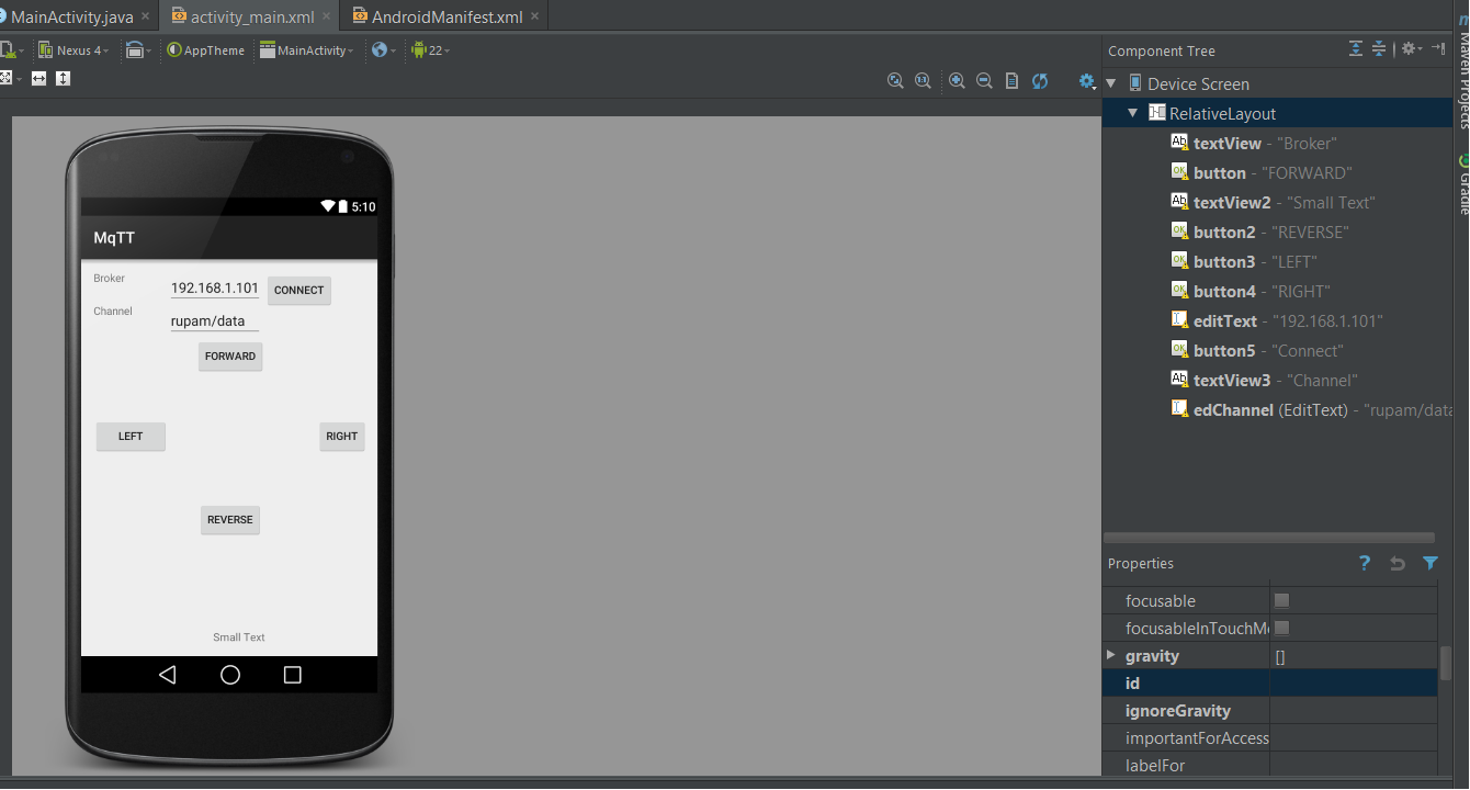
activity_main.xml layout
<?xml version="1.0" encoding="utf-8"?>
<RelativeLayout xmlns:android="http://schemas.android.com/apk/res/android"
    xmlns:app="http://schemas.android.com/apk/res-auto"
    android:layout_width="match_parent"
    android:layout_height="match_parent"
    android:paddingBottom="@dimen/activity_vertical_margin"
    android:paddingLeft="@dimen/activity_horizontal_margin"
    android:paddingRight="@dimen/activity_horizontal_margin"
    android:paddingTop="@dimen/activity_vertical_margin">

    <Button
        android:id="@+id/forward_button"
        android:layout_width="wrap_content"
        android:layout_height="wrap_content"
        android:text="Forward" />

    <Button
        android:id="@+id/reverse_button"
        android:layout_width="wrap_content"
        android:layout_height="wrap_content"
        android:text="Reverse"
        android:layout_below="@id/forward_button" />

    <Button
        android:id="@+id/right_button"
        android:layout_width="wrap_content"
        android:layout_height="wrap_content"
        android:text="Right"
        android:layout_below="@id/reverse_button" />

    <Button
        android:id="@+id/left_button"
        android:layout_width="wrap_content"
        android:layout_height="wrap_content"
        android:text="Left"
        android:layout_below="@id/right_button" />

    <Button
        android:id="@+id/stop_button"
        android:layout_width="wrap_content"
        android:layout_height="wrap_content"
        android:text="Stop"
        android:layout_below="@id/left_button" />

    <Button
        android:id="@+id/no_button"
        android:layout_width="wrap_content"
        android:layout_height="wrap_content"
        android:text="No"
        android:layout_below="@id/stop_button" />

</RelativeLayout>
In this layout, we use a RelativeLayout to place the buttons for controlling the car. We define six buttons for forward, reverse, right, left, stop, and no commands. Each button is placed below the previous one using the layout_below attribute.
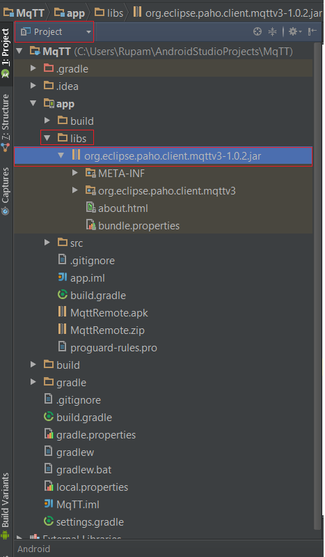
Adding the MQTT JAR File to the Android Project
To use the MQTT library in our Android app, we need to download the MQTT JAR file and add it to our project. Create a new folder called libs in the physical directory of your project, and paste the JAR file into it. Once you've done this, you should be able to see the JAR file under the Project tab in Android Studio.
Controlling the Car with MQTT
Recall that our Node.js app has six states: FORWARD, REVERSE, LEFT, RIGHT, STOP, and NO. To control the car, we need to send these commands to the MQTT broker. Since the remote control doesn't have six buttons, we'll attach the MQTT publish method to the touch event instead. When the user presses a button, we'll send the corresponding command to the MQTT broker. When the user releases the button, we'll send the NO command to stop the car.
Connecting to the MQTT Broker
In our MainActivity.java class, we'll create a method called Connect() to connect to the MQTT broker. Since Android doesn't allow network calls from the main thread, we'll create a new class called ConnectionClass that extends AsyncTask and connects to the broker in the doInBackground method.
Here's the code for the ConnectionClass:
public class ConnectionClass extends AsyncTask<String, String, String> {
    Exception exc = null;

    @Override
    protected void onPreExecute() {
        super.onPreExecute();
    }

    @Override
    protected String doInBackground(String... params) {
        try {
            if (Looper.myLooper() == null) {
                Looper.prepare();
            }
            sampleClient = new MqttClient(broker, clientId, persistence);

            connOpts = new MqttConnectOptions();
            connOpts.setCleanSession(true);
            IMqttToken imt = sampleClient.connectWithResult(connOpts);

            Log.d("MQTT MODULE.....", "....DONE..." + sampleClient.getServerURI() + "--" + imt.getResponse().getPayload());

            if (sampleClient.isConnected()) {
                return "CONNECTED";
            } else {
                return "Connection Failed.....";
            }
        } catch (Exception ex) {
            Log.d("MQTT MODULE", "CONNECTion FAILED " + ex.getMessage() + " broker: " + broker + " clientId " + clientId);

            return "FAILED " + ex.getMessage();
        }
    }

    @Override
    protected void onPostExecute(String result) {
        super.onPostExecute(result);

        if (result!= null) {
            if (result.equals("CONNECTED")) {
                isConnected = true;
            } else {
                isConnected = false;
            }
            tv2.setText(result);
            Toast.makeText(MainActivity.this, result, Toast.LENGTH_LONG).show();
        }
    }
}
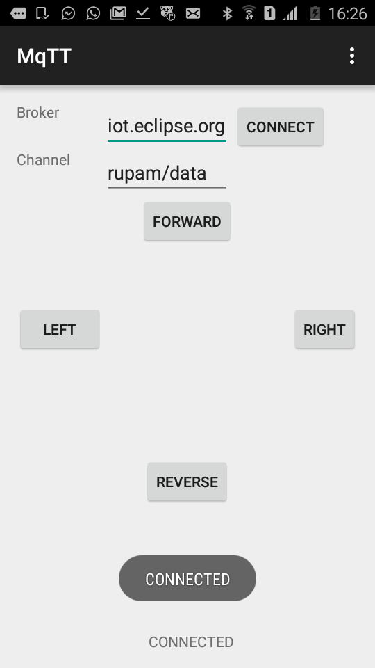
In the postExecute method, we'll display the result of the connection request with a Toast message. When the btnConnect button is clicked, we'll execute the ConnectionClass object, which will trigger the connection to the MQTT broker in the background.
Handling Button Clicks and Touch Events
When the btnConnect button is clicked, we execute the ConnectionClass object, which triggers the connection to the MQTT broker in the background.
Instead of creating six buttons for the six states, we create four buttons and attach a setOnTouchListener to each button. This allows us to emulate the behavior of the physical remote control, where the car is in a certain state when a button is pressed and stops when the button is released.
Here is the initialization of the UI components in MainActivity.java:
b = (Button)findViewById(R.id.button);
b2=(Button)findViewById(R.id.button2);
b3=(Button)findViewById(R.id.button3);
b4=(Button)findViewById(R.id.button4);
btnConnect=(Button)findViewById(R.id.button5);
edServer=(EditText)findViewById(R.id.editText);
edChannel=(EditText)findViewById(R.id.edChannel);
topic=edChannel.getText().toString().trim();

btnConnect.setOnClickListener(new OnClickListener() {
    @Override
    public void onClick(View v) {
        broker="tcp://"+edServer.getText().toString().trim()+":1883";
        topic=edChannel.getText().toString().trim();
        ConnectionClass con=new ConnectionClass();
        con.execute();
    }
});

b.setOnTouchListener(this);
b2.setOnTouchListener(this);
b3.setOnTouchListener(this);
b4.setOnTouchListener(this);
tv2=(TextView)findViewById(R.id.textView2);
Handling Touch Events
To handle touch events, we make the MainActivity.java class implement the OnTouchListener interface. In the onTouch method, we handle MotionEvent.ACTION_DOWN and MotionEvent.ACTION_CANCEL to trigger MQTT messages.
@Override
public boolean onTouch(View v, MotionEvent event) {
    Button b=(Button)v;
    switch (event.getAction() & MotionEvent.ACTION_MASK) {
        case MotionEvent.ACTION_DOWN:
            v.setPressed(true);
            tv2.setText("ENTERED:"+b.getText()+"-" + (new Date()).toString());
            Send(b.getText().toString());
            break;
        case MotionEvent.ACTION_UP:
        case MotionEvent.ACTION_OUTSIDE:
        case MotionEvent.ACTION_CANCEL:
            v.setPressed(false);
            tv2.setText("LEFT:" + b.getText() + "-" + (new Date()).toString());
            if(b.getText().toString().trim().equals("LEFT")||b.getText().toString().trim().equals("RIGHT"))
                Send("NO");
            else
                Send("STOP");
            break;
        //...
    }
    return true;
}
Sending MQTT Messages
The Send method is responsible for sending MQTT messages to the broker. We check if the sampleClient is connected or not, and if connected, we send the message to the channel specified by the edChannel EditText.
void Send(String content) {
    final String data=content;
    AsyncTask.execute(new Runnable() {
        @Override
        public void run() {
            try {
                if(isConnected) {
                    MqttMessage message = new MqttMessage(data.getBytes());
                    message.setQos(qos);
                    sampleClient.publish(topic, message);
                }
                Log.d("MQTT MODULE",data+" SENT");
            } catch(Exception ex) {
                //...
            }
        }
    });
}
Adding Internet Permission
Finally, don't forget to add the INTERNET permission to your Android app's manifest file:
<uses-permission android:name="android.permission.INTERNET"/>
With this, you're ready to run your Android app and control your RC car using MQTT!
Intel RealSense C# Client for Controlling the Car with Hand Gesture, Emotion, and Speech
Intel RealSense is a technology that enables short-range accurate gesture recognition. It was initially introduced with great fanfare, and its potential use cases were thought to be limited to gaming. However, with time, augmented reality and 3D scanning have become more prominent use cases. Intel is now backing RealSense as a key technology for IoT applications, and it is being used in various robots, including the Asus Zenbo.
The Zenbo robot uses gesture technology to locate physical objects, and it can be controlled with voice commands and hand gestures. For example, saying "Zenbo get me that towel" while pointing to the towel can guide the robot to retrieve it.
I believe that combining voice and hand gesture is an ideal input modality for physical objects that are traditionally controlled with remotes and switches. Therefore, I decided to develop a RealSense app for our car.
The best part about our design is that new apps can be added to the architecture without changing any hardware. For instance, we can develop a new Android app that controls the left and right direction of the car using the accelerometer. All we need to do is push the detected gesture into our MQTT channel.
The RealSense app is an independent unit that can be used alongside our smartphone Android app or as a standalone app. However, the biggest challenge is to create a multi-modality app that can take voice, face, and hand gesture inputs simultaneously.
Working with RealSense can be challenging, especially when it comes to handling multiple gestures. The SDK provides separate samples for hand tracking, 3D segmentation, speech synthesis, and controlling desktop UIs with RealSense. To overcome this challenge, I created a class called TheUltimateRealSense that combines face, segmentation, hand tracking, and speech recognition (and speech synthesis).
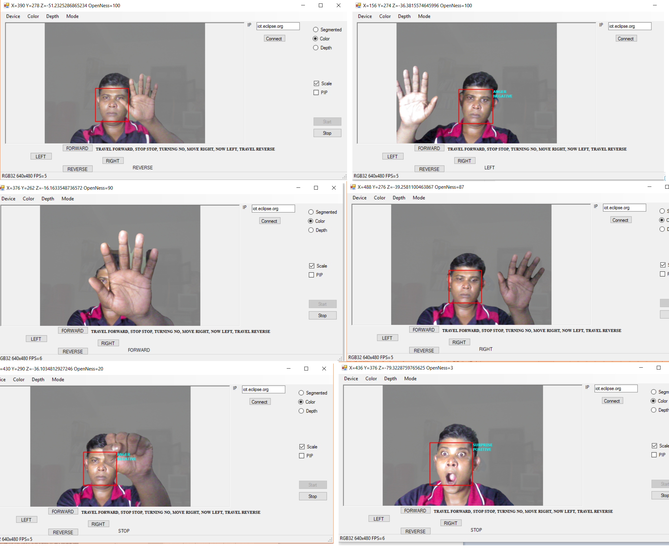
Let's take a look at the various gestures and how they work in the context of our control mechanism.
Gestures and Workflow
- Voice commands can be generated for FORWARD, REVERSE, LEFT, RIGHT, STOP, and NO.
- When a voice command is generated for FORWARD, the car's forward movement will remain active.
- The car can be stopped using a voice gesture, a hand close gesture, or a Surprise emotion (I'll explain the logic behind selecting this emotion for stopping later).
- The user can bring their hand near the camera and away from the camera to generate forward and reverse commands, respectively.
- Moving the hand to the left or right generates left and right movement commands, respectively. If the hand is nearer to the camera while moving to the right side, it generates a FORWARD+RIGHT command. Similarly, moving the hand to the right side at a position away from the camera generates a REVERSE+RIGHT command.
- When the car's movement is activated by a hand gesture, dropping the hand (no hand detected) generates a STOP command. However, if the car was started with a voice command, dropping the hand will not stop the car. This means that the user can give a voice command and sit back and relax.
Creating a New Thread for RealSense Integration
In the MainForm.cs file, we create a new thread called DoRendering to handle the RealSense integration.
private void Start_Click(object sender, EventArgs e)
{
    Start.Enabled = false;
    Stop.Enabled = true;
    stop = false;
    System.Threading.Thread thread = new System.Threading.Thread(DoRendering);
    thread.Start();
    System.Threading.Thread.Sleep(5);
}
Initializing the RealSense Class
We create an instance of the TheUltimateRealSense class, passing the MainForm instance to its constructor. This allows the class to access the elements of MainForm.
PXCMSenseManager pp; pp.QueryHand(), pp.Query3DSeg(), pp.QuerySample(), pp.QueryEmotion(), pp.QueryHandSample() are called to check if the installed SDK components support these features and if the attached camera can be used for these implementations.
StreamColorDepth Method
The StreamColorDepth method is where all the detection takes place.
private void DoRendering()
{
    rs = new TheUltimateRealSenseClass(this, session, StreamMode.LIVE, ColorType.SEGMENTED);
    rs.timer = new FPSTimer(this);
    rs.OneTimeInitializationBeforeLooping();
    rs.Speak("Welcome to Smart I o T RC Car Demo", 80, 100, 80);
    int choice = 0; // 0->segmented 1->hand
    while (!rs.Stop)
    {
        bool success = rs.StreamColorDepth(true);
        if (success)
        {
            lock (this)
            {
                if (choice == 0)
                {
                    // bitmaps[index] = rs.bitmaps[index]; // for segmented image
                    bitmaps[index] = rs.DisplayJoints(rs.nodes, rs.numOfHands, rs.bitmaps[index], true, true, true);
                }
                if (choice == 1)
                {
                    if (rs.labeledBitmap!= null)
                    {
                        // bitmaps[index] = rs.DisplayJoints(rs.nodes, rs.numOfHands, rs.labeledBitmap, true, true, true);
                        bitmaps[index] = rs.labeledBitmap;
                    }
                }
                if (rs.emotionData!= null)
                    bitmaps[index] = rs.DisplayEmotionSentimentFaceLocation(rs.emotionData, bitmaps[index]);
            }
            MainPanel.Invalidate();
            UpdatePanel();
        }
    }
    this.Invoke(new DoRenderingEnd(
        delegate
        {
            rs.Finish();
            Start.Enabled = true;
            Stop.Enabled = false;
            MainMenu.Enabled = true;
            if (closing) Close();
        }
    ));
}
Segmenting the Image
In the StreamColorDepth method, we first segment the image using the Query3DSeg method.
if (pp.AcquireFrame(synced) < pxcmStatus.PXCM_STATUS_NO_ERROR)
{
    projection.Dispose();
    return false;
}
frameCounter++;
/* Get Segmentation image from the User Segmentation video module */
PXCM3DSeg seg = pp.Query3DSeg();
if (seg == null)
{
    pp.ReleaseFrame();
    projection.Dispose();
    pp.Close();
    pp.Dispose();
    UpdateStatus("Error: 3DSeg is not available");
    return false;
}
PXCMImage segmented_image = seg.AcquireSegmentedImage();
if (segmented_image == null)
{
    pp.ReleaseFrame();
    projection.Dispose();
    pp.Close();
    pp.Dispose();
    UpdateStatus("Error: 3DSeg did not return an image");
    return false;
}
Hand Gesture Recognition
Once we segment the image, we query for HandSample, which returns a segmented hand image (if a hand is detected). If a segmented hand image is present (which we do not use in our case), then we loop through the number of detected hands and query for hand data, which returns hand statistics in ihandData. These statistics are passed to HandGestureToCar for translating hand position into gestures specific to car control.
#region hand gesture related part
if (handData!= null)
{
    handData.Update();
}

sample = pp.QueryHandSample();
if (sample!= null && sample.depth!= null)
{
    DisplayPicture(sample.depth, handData); // working
    // DisplayPicture(segmented_image, handData);
    if (handData!= null)
    {
        frameNumber = liveCamera? frameCounter : pp.captureManager.QueryFrameIndex();

        // DisplayJoints(handData);
        #region display joints
        PXCMHandData handOutput = handData; long timeStamp = 0;
        // Iterate hands
        nodes = new PXCMHandData.JointData[][] { new PXCMHandData.JointData[0x20], new PXCMHandData.JointData[0x20] };
        numOfHands = handOutput.QueryNumberOfHands();
        if (numOfHands == 0)
        {
            form.HandGestureTocar(posX, posY, posZ, 0);
        }
        for (int i = 0; i < numOfHands; i++)
        {
            // Get hand by time of appearance
            // PXCMHandAnalysis.HandData handData = new PXCMHandAnalysis.HandData();

            if (handOutput.QueryHandData(PXCMHandData.AccessOrderType.ACCESS_ORDER_BY_TIME, i, out ihandData) == pxcmStatus.PXCM_STATUS_NO_ERROR)
            {
                if (ihandData!= null)
                {
                    HandOpen[i] = ihandData.QueryOpenness();
                    var pt = ihandData.QueryMassCenterImage();
                    posX = pt.x;
                    posY = pt.y;
                    posZ = ihandData.QueryMassCenterWorld().y * 1000;
                    form.Invoke((MethodInvoker)delegate
                    {
                        form.Text = String.Format("X={0} Y={1} Z={2} OpenNess={3}", posX, posY, posZ, HandOpen[i]);
                        form.HandGestureTocar(posX, posY, posZ, HandOpen[i]);
                        // your UI update code here. e.g. this.Close(); Label1.Text="something";
                    });

                    // Iterate Joints
                    for (int j = 0; j < 0x20; j++)
                    {

                        // ihandData.QueryTrackedJoint((PXCMHandData.JointType)j, out jointData);
                        // nodes[i][j] = jointData;

                    } // end iterating over joints
                }
            }
        } // end iterating over hands

        #endregion
    }
}
Translating Hand Gestures to Car Control
The HandGestureTocar method translates the hand gestures into car control commands.
public void HandGestureTocar(double x, double y, double z, int openness)
{
    if (openness > 30)
    {
        // if (Math.Abs(lastY - y) > 60)
        {
            if (x < 250)
            {
                gesture = "LEFT";
            }
            else if (x > 420)
            {
                gesture = "RIGHT";
            }
            else
            {
                if (Math.Abs(z) < 28)
                {
                    if (lastGesture.Equals("LEFT") || lastGesture.Equals("RIGHT"))
                    {
                        gesture = "NO";
                    }
                    else
                    {
                        gesture = "FORWARD";
                    }
                }
                if (Math.Abs(z) > 40)
                {
                    if (lastGesture.Equals("LEFT") || lastGesture.Equals("RIGHT"))
                    {
                        gesture = "NO";
                    }
                    else
                    {
                        gesture = "REVERSE";
                    }
                }
            }
            lastY = y;
        }
    }
    else
    {
        lastY = 0;
        if (!TheUltimateRealSenseClass.isVoiceGesture)
            gesture = "STOP";
    }

    if (!gesture.Equals(lastGesture))
    {
        label1.Invoke((MethodInvoker)delegate
        {
            label1.Text = gesture;
        });

        if (connected)
        {
            lastGesture = gesture;

            lastY = 0;
            PublishMQTTData(gesture);

        }
    }
}
Intelligent Car Control with Emotion Detection
Imagine being in a situation where your car is about to collide with a precious gift your wife gave you on your anniversary. What would you do? In the heat of the moment, it's easy to forget what to do. Fortunately, with Intel RealSense technology, we can detect emotions and react accordingly. In this tutorial, we'll explore how to use facial expression recognition to control a car.
Analyzing Emotions with RealSense
We'll utilize the DisplayEmotionSentimentFaceLocation method from TheUltimateRealSenseClass to analyze the emotion and generate a STOP command if the detected emotion is SURPRISE. This method first queries the number of faces in the scene using QueryNumFaces, and then for each face, it calls QueryAllEmotionData to retrieve emotion data. The emotion data is then rendered using the DrawLocation method.
public Bitmap DisplayEmotionSentimentFaceLocation(PXCMEmotion ft, Bitmap bitmap)
{
    int numFaces = ft.QueryNumFaces();
    for (int i = 0; i < numFaces; i++)
    {
        PXCMEmotion.EmotionData[] arrData = new PXCMEmotion.EmotionData[NUM_EMOTIONS];
        if (ft.QueryAllEmotionData(i, out arrData) >= pxcmStatus.PXCM_STATUS_NO_ERROR)
        {
            bitmap = DrawLocation(arrData, bitmap);
        }
    }
    return bitmap;
}

private Bitmap DrawLocation(PXCMEmotion.EmotionData[] data, Bitmap bitmap)
{
    //...
    if (EmotionLabels[epidx].Equals("SURPRISE"))
    {
        form.PublishMQTTData("STOP");
    }
    //...
}
Exploring Other Possibilities
You can experiment with the code to explore other possibilities, such as driving the car with a SMILE gesture or moving the car with face movement. The possibilities are endless with emotion detection and machine learning!
How About Voice?
In this section, we'll explore the voice modality, which is an essential component of our DIY smart hardware project. It's crucial to understand the limitations of the RealSense speech recognition engine, particularly when it comes to detecting single-phrase commands. The engine excels at recognizing compound phrases, even with a large dictionary, but struggles with single-phrase commands, even with a limited vocabulary.
This limitation is partly due to the shared session between different RealSense algorithms. When you start speaking, the handle might be with the hand or face module, making it challenging for the voice module to capture small phrases. To overcome this, we'll use compound phrases that ensure the voice module captures the command accurately.
We define a string array called cmds and initialize it with the voice commands.
public string[] cmds = new string[] { "STRAIGHT FORWARD", "STOP STOP", "NO NO", "MOVE RIGHT", "MOVE LEFT", "COME REVERSE" };
When the TheUltimateRealSense class is initialized, the OneTimeInitVoice() method is called, which sets up the voice module or speech recognition. We create an instance of PXCMSpeechRecognition and attach it to the current session. We then build a grammar for recognition using the cmds array and set the OnRecognition() event handler, which is triggered when a phrase is recognized.
public void OneTimeInitVoice(PXCMSession session)
{
// Create the AudioSource instance
source = session.CreateAudioSource();

// Set audio volume to 0.2
source.SetVolume(0.2f);

// Set Audio Source
source.SetDevice(vDevices[selectedVdevice]);

// Set Module
PXCMSession.ImplDesc mdesc = new PXCMSession.ImplDesc();
mdesc.iuid = vModules[selectedVmodule];

pxcmStatus sts = session.CreateImpl<PXCMSpeechRecognition>(out sr);
if (sts >= pxcmStatus.PXCM_STATUS_NO_ERROR)
{
    // Configure
    PXCMSpeechRecognition.ProfileInfo pinfo;
    sr.QueryProfile(0, out pinfo);
    sr.SetProfile(pinfo);

    if (cmds!= null && cmds.GetLength(0)!= 0)
    {
        // voice commands available, use them
        sr.BuildGrammarFromStringList(1, cmds, null);
        sr.SetGrammar(1);
    }

    // Initialization
    PrintStatus("Init Started");
    PXCMSpeechRecognition.Handler handler = new PXCMSpeechRecognition.Handler();
    handler.onRecognition = OnRecognition;
    handler.onAlert = OnAlert;

    sts = sr.StartRec(source, handler);
    if (sts >= pxcmStatus.PXCM_STATUS_NO_ERROR)
    {
        PrintStatus("Init OK");
    }
    else
    {
        PrintStatus("Failed to initialize");
    }
}
else
{
    PrintStatus("Init Failed");
}
}
When a voice command is recognized, the OnRecognition() method is called, which publishes an MQTT message.
void OnRecognition(PXCMSpeechRecognition.RecognitionData data)
{
string s = data.scores[0].sentence;
try
{
s = s.Split(new char[] {'' })[1];
isVoiceGesture = true;
VoiceGesture = s;

    form.PublishMQTTData(s);
    if (s.Equals("STOP") || s.Equals("NO"))
    {
        isVoiceGesture = false;
    }
}
catch { }
}
The PublishMQTTData() method is responsible for publishing the MQTT message. To avoid flooding the broker with repeated commands, we only publish a new message if the detected gesture or generated command is different from the previous one.
string lastSent = "";
public void PublishMQTTData(string command)
{
label1.Invoke((MethodInvoker)delegate
{
label1.Text = command;
});

if (connected)
{
    if (!lastSent.Equals(command))
    {
        if (command.Equals("STOP") || command.Equals("NO"))
        {
            TheUltimateRealSenseClass.isVoiceGesture = false;
        }
        mqtt.Publish(topic, GetBytes(command), 0, false);
        lastSent = command;
    }
}
}
With this implementation, you can experiment with different voice commands and workflows to control your DIY EaseCar project.
Building the Prototype: Integrating Hardware and Software
So far, we've successfully hacked a remote control car, connected it to an Intel Edison board, and experimented with its capabilities. However, our project's ultimate goal is to create an automated navigation system for the car, complete with a camera attachment. To achieve this, we need to overcome a significant challenge: powering the Edison board and camera with a reliable power source.
The Edison board requires a 12V 1.5A supply, which is not feasible with the standard 3V-6.5V @ 300mA-600mA external batteries used in RC cars. To address this issue, we'll need to connect the Edison board to an external battery and modify the car's power supply.
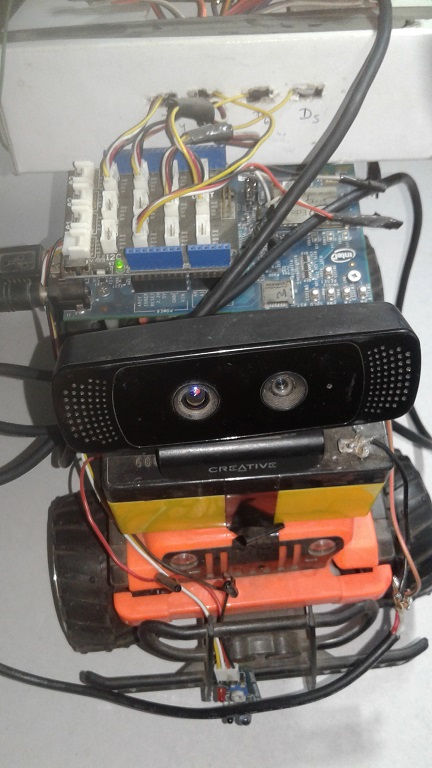
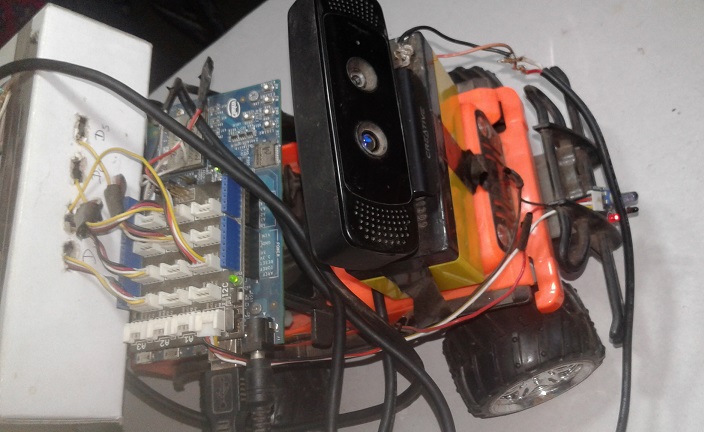
For this project, I chose a Jeep from my son's collection (with his reluctant permission, of course!). To automate the car's navigation and add collision avoidance capabilities, we'll incorporate an infrared (IR) sensor. This sensor has three pins: Vcc, Gnd, and Vout, which outputs an analog voltage that varies depending on the distance of obstacles from the module. When an obstacle approaches, the voltage increases.
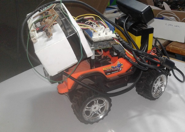
To connect the IR sensor to the Edison board, we'll need to cut another cable and plug it into a Grove slot. Then, we'll connect the Red wire to Vcc, Black to Gnd, and Yellow to Vout. Next, we'll mount the IR sensor on the front of the car, along with the Edison board, transistor array board with RF transmitter, and a 12V battery.
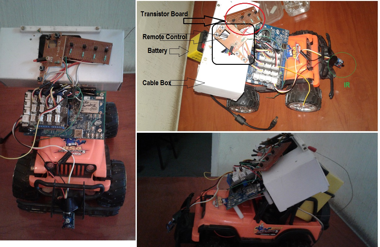
The resulting setup may not be aesthetically pleasing, but it's functional. Hopefully, some of you can improve upon this design using better mechatronic components.
Implementing Collision Avoidance Logic
Now that we have the hardware in place, we need to develop a collision avoidance logic that can control the car's speed and direction. Since the car is heavier at the rear, high-speed reverse maneuvers can cause it to become unstable. To mitigate this, we'll use pulse-width modulation (PWM) to control the motors, connecting the forward and reverse transistors to D5 and D6, respectively.
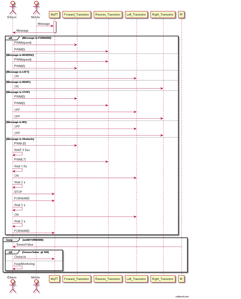
The IR sensor returns a high value when an obstacle is detected. In an ideal scenario, the car would stop upon detection. However, since we want to broadcast our party live on YouTube, we need the car to alter its route instead of stopping. We'll achieve this by implementing a sequence of actions: REVERSE+RIGHT, followed by FORWARD, and then a slight RIGHT and LEFT turn to straighten the car.
The message exchange architecture for automatic navigation is illustrated below. We'll need to modify our code to integrate this message exchange structure, which will enable the car to navigate autonomously while avoiding obstacles.
var mqtt    = require('mqtt');
var client  = mqtt.connect('mqtt://192.168.1.9');
var mraa = require('mraa')
var SPEED=1
////////////////// Remote Pins//////////////////
var fPin = new mraa.Gpio(6)

var bPin = new mraa.Gpio(5)
var rPin = new mraa.Gpio(3)
var lPin = new mraa.Gpio(4)
var sensor=new mraa.Aio(0);

//////////////Set up Pins/////////////////////////
fPin.dir(mraa.DIR_OUT)
bPin.dir(mraa.DIR_OUT)

rPin.dir(mraa.DIR_OUT)
lPin.dir(mraa.DIR_OUT)
//////////////// Initialize///////////////////
fPin.write(0)
bPin.write(0)
rPin.write(0)
lPin.write(0)

/////////////////////////////////
client.subscribe('rupam/data/#')
client.handleMessage=function(packet,cb)
{
var payload = packet.payload.toString()
 if (payload === 'FORWARD')
 {

 State=1;
 bPin.write(0);
 fPin.write(SPEED)

 }
 if (payload === 'REVERSE')
{

 fPin.write(0);

 bPin.write(SPEED);

}
 if (payload === 'RIGHT')
 {
lPin.write(0);
 rPin.write(1)

 }
 if (payload === 'LEFT')
 {
rPin.write(0);
 lPin.write(1)

 }
 if (payload === 'STOP')
 {
 fPin.write(0)
 rPin.write(0)
bPin.write(0)
lPin.write(0)

 }
 if (payload === 'NO')
 {
 rPin.write(0)
 lPin.write(0)
 }


console.log(payload)
cb()
}

Loop();
var numRight=0;
var Obstacle=0;
var State=0;
function Loop()
{
setTimeout(Loop,100);
var a=sensor.read();
if(a>100)
{
  if(Obstacle==0)
  {
   Obstacle=30;
   fPin.write(0);
   //client.publish('rupam/data/','STOP');
  }
//client.publish('rupam/data/','RIGHT');
//numRight++;
}
else
{
 if(numRight>0)
  {
   client.publish('rupam/data/','LEFT');
   numRight--;
  }
}
if(Obstacle>1)
{
 Obstacle--;


}
if(Obstacle==1)
{
  Obstacle--;
  if(State==1)
  {
    State==0;
    client.publish('rupam/data/','REVERSE');
    client.publish('rupam/data/','LEFT');
    setTimeout(func, 2000);
       function func() {
           client.publish('rupam/data/','FORWARD');
           client.publish('rupam/Data/','RIGHT');

           setTimeout(f,200);
               function f()
                  {
                    client.publish('rupam/data/','NO');
                  }
        }
  }
}
console.log(a);
}
Broadcasting Live Video Feed from EaseCar to YouTube
To begin, ensure that your camera is properly configured as described in the Biometric Locker article.
For YouTube live streaming, we'll employ the following architecture:
First, install the mjpg-streamer package on your Intel Edison:
opkg install mjpg-streamer
Next, launch the streamer in one of the SSH Edison shell sessions:
mjpg_streamer -i "input_uvc.so -y -n -f 30 -r 320x240" -o "output_http.so -p 8090 -n -w /www/webcam"
This will initiate video streaming on port 8090. Verify the stream by accessing the following URL in a modern browser like Chrome:
http://<Edison_IP_address>:8090?action=stream
Replace
Now, log in to your YouTube account and navigate to the Creator Studio (note that you need a verified YouTube account for live streaming).
On the left-hand side, select the "Live Stream" option. Your stream will be opened, and you'll see the RTMP stream link and a key at the bottom. Copy the key.
Important Note: Since mjpg-streamer only streams video without audio, and YouTube doesn't allow audio-less streams, we need to add audio to the incoming stream and re-encode the video before sending it to YouTube.
To achieve this, we'll utilize the powerful ffmpeg tool for video mixing, audio capturing, and other video-audio related tasks.
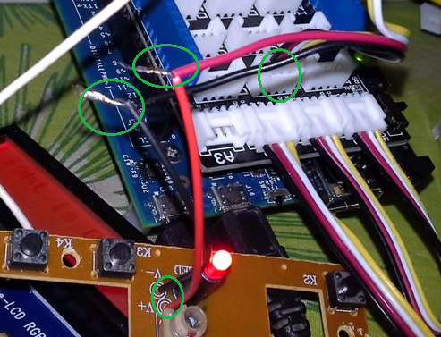
First, identify the list of audio recording devices using:
ffmpeg.exe -list_devices true -f dshow -i dummy
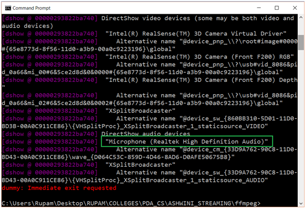
Your microphone will be listed, similar to the green marked rectangle. Copy the device name.
Test audio recording using:
ffmpeg.exe -f dshow -i audio="Microphone (Realtek High Definition Audio)" outputAud.wav
Finally, use the following ffmpeg command to stream your Edison car's video feed to YouTube:
ffmpeg.exe -f dshow -i audio="Microphone (Realtek High Definition Audio)" -f mjpeg -r 8 -i http://<Edison_IP_address>:8090/video.jpg -acodec libmp3lame -ar 44100 -b:a 128k -profile:v baseline -s 320x240 -bufsize 2048k -vb 400k -maxrate 800k -deinterlace -vcodec libx264 -preset medium -g 30 -r 30 -f flv "rtmp://a.rtmp.youtube.com/live2/<YOUR_KEY>
Replace
After a 10-second delay, your stream will start appearing on YouTube, as shown in:
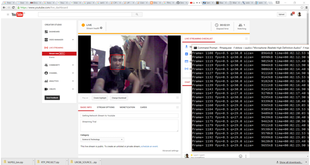
I successfully broadcasted an Intel event (Intel Software Innovator's meet in Bangalore, India) using this setup. You can watch the recorded stream here: Intel Software Innovator's Meet- Live Streaming from Edison (now a recorded version).
That's it! You've successfully set up live streaming from your EaseCar to YouTube. Now, you can move your car using gestures, smart phone, or voice commands and live telecast events to YouTube.
Here are some amateur photos I captured using a not-so-high-definition camera, giving you an idea of the hack and the cool car we built with full IoT and gesture integration.
Summary
As I reflect on this project, I am reminded of the humble beginnings that date back to about a year ago. My initial goal was to create a fun and engaging experience for my son by hacking RC cars. Little did I know that this project would mark the beginning of my journey from embedded-IoT to pure IoT. I am grateful to Intel for providing me with the necessary kits and resources to explore the vast possibilities of IoT.
The transformation of a simple RC car into a feature-rich robot with real-time capabilities has been a remarkable journey. The Intel Edison-Youtube broadcaster project, although a separate entity, has been an essential component in achieving a complex software and hardware stack integration. This integration has allowed me to test the capabilities of Intel's IoT features and showcase their potential.
While this version of the project still faces performance issues, such as rapid battery drainage and jitter when mobile phones are in close proximity, I believe it provides a solid foundation for your next IoT project. Whether you're looking to create a fun project for your kids or showcase your skills to friends, this project can serve as a valuable starting point.
I hope that this tutorial has inspired you to explore the world of IoT and has provided you with the necessary guidance to bring your projects to life.